Do you have a question about the MSI MS-7042 and is the answer not in the manual?
Details the technical specifications of the MS-7042 mainboard, including chipsets and memory support.
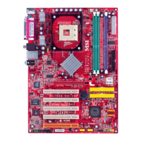
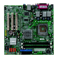
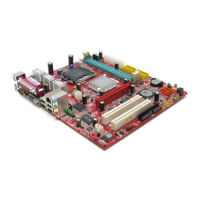
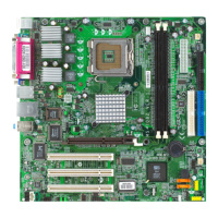
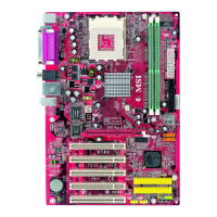
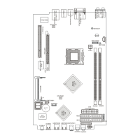
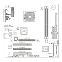
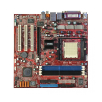
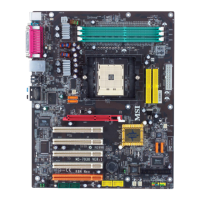
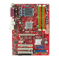
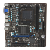
Visual guide identifying key components and connectors on the mainboard.
Instructions for installing the CPU and its cooling fan to prevent overheating.
Guide for installing DDR SDRAM modules and understanding memory combinations.
Details on connecting ATX 20-pin and 12V CPU power connectors.
Description of rear panel connectors like PS/2, Parallel, LAN, and USB.
Explains USB, LAN, and IEEE1394 port functionality and pin definitions.
Pin definitions for COM ports and audio connectors.
Details the 25-pin female centronic parallel port connector.
Connectors for Floppy Disk Drive (FDD1) and CPU/System Fan (FANCPU1).
Information on IDE1 and IDE2 connectors for hard drives and CD-ROMs.
Pin definitions for front panel audio (JAUD1), game (JGP1), and line-in (JL_IN1).
Connectors for front panel switches (JFP1) and USB headers (JUSB1/JUSB2).
Explains the use of jumpers, specifically the CMOS clear jumper (JBAT1).
Details the AGP and PCI slots for expansion cards.
| Brand | MSI |
|---|---|
| Model | MS-7042 |
| Category | Motherboard |
| Language | English |