2-6
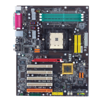
MS-7021 ATX Mainboard
Front Panel Audio Connector: JAUD1
You can connect an optional audio connec-
tor to the JAUD1 front panel audio connector.
JAUD1 is compliant to Intel
®
Front Panel I/O Con-
nectivity Design Guide.
JAUD1
1
2
10
9
PIN SIGNAL DESCRIPTION
1 AUD_MIC Front panel microphone input signal
2 AUD_GND Ground used by analog audio circuits
3 AUD_MIC_BIAS Microphone power
4 AUD_VCC Filtered +5V used by analog audio circuits
5 AUD_FPOUT_R Right channel audio signal to front panel
6 AUD_RET_R Right channel audio signal return from front panel
7 HP_ON Reserved for future use to control headphone amplifier
8 KEY No pin
9 AUD_FPOUT_L Left channel audio signal to front panel
10 AUD_RET_L Left channel audio signal return from front panel
JAUD1 Pin Definition
MSI Reminds You...
If you don’t want to connect to the front audio
header, pins 5 & 6, 9 & 10 have to be jumpered in
order to have signal output directed to the rear
audio ports. Otherwise, the Line-Out connector on
the back panel will not function.
5
6
10
9
Pin Description Pin Description
1 VCC 2 VCC
3 USB0- 4 USB1-
5 USB0+ 6 USB1+
7 GND 8 GND
9 Key 10 USBOC
JUSB1/JUSB2 Pin Definition
Front USB Connectors: JUSB1 & JUSB2
The mainboard provides two USB2.0
pinheaders for users to connect to optional
USB2.0 ports. They are compliant to Intel
®
I/O
Connectivity Design Guide.
1
9
2
10
JUSB1/JUSB2
(USB 2.0/Intel spec)