Do you have a question about the MSI MS-7174 and is the answer not in the manual?
Overview of the mainboard's technical specifications, including CPU, chipset, and memory.
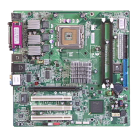
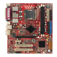
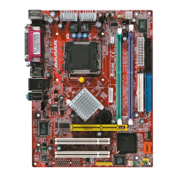
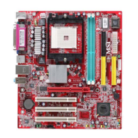
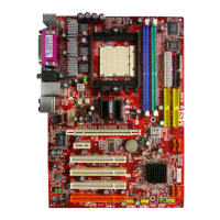
Visual diagram illustrating the placement of various connectors and components on the mainboard.
A visual guide identifying key components and connectors on the mainboard with page references.
Information on Intel Pentium 4 Prescott processors and the LGA775 socket, including installation advice.
Step-by-step instructions for correctly installing the CPU and its cooling fan to prevent overheating.
Overview of the mainboard's memory support, including DDR2 SDRAM and installation requirements.
Details on how memory modules can be installed in various combinations across the slots.
Step-by-step guide on how to properly insert DDR DIMM modules into the slots.
Information regarding ATX power supply connectors, ATX1 (24-pin) and ATX_IN (12V).
Instructions for connecting the ATX 24-pin power supply, including pin alignment and compatibility.
Details on the ATX 12V power connector used to supply power directly to the CPU.
Overview of the connectors available on the mainboard's back panel.
Pin definition and usage of the PS/2 mouse and keyboard connector.
Information on the DB 15-pin female connector for connecting a VGA monitor.
Details on Universal Serial Bus (USB) ports, including OHCI compliance and port descriptions.
Information on the RJ-45 jack for network connectivity and its transfer speeds.
Explains the audio jacks for stereo and 7.1-channel output, plus SPDIF connectors.
Details on the 25-pin centronic connector used as a standard printer port.
Information on the FDD1 connector supporting various floppy disk drive types.
Details on connecting CPU and system cooling fans, including pinouts and power requirements.
Information on the IDE1 connector for connecting up to two Ultra ATA hard drives.
Details the pin header intended for internal debugging purposes only.
Explains the SATA1 and SATA2 interface ports for high-speed serial ATA hard drives.
Details the JFP1 connector for connecting front panel switches, LEDs, and power indicators.
Information on the JAUD1 connector for front panel audio connections and jack detection.
Details the USB 2.0 pin headers for connecting front USB ports to high-speed peripherals.
Information on the AUX_IN1 connector for DVD add-on cards with Line-in functionality.
Details the JCD1 connector for CD-ROM audio input.
Information on optional IEEE 1394 pin headers for FireWire connectivity.
Instructions for clearing CMOS settings using the JBAT1 jumper by changing its position.
Instructions for clearing the BIOS password using the JPWD1 jumper by altering its configuration.
Details on the PCI Express x16 slot for high-bandwidth expansion cards.
Information on standard PCI bus slots for adding expansion cards.
| Form Factor | Micro ATX |
|---|---|
| CPU Socket | Socket 939 |
| Chipset | ATI Radeon Xpress 200 |
| Memory Type | DDR |
| Max Memory | 4GB |
| Storage Interfaces | 2 x SATA, 2 x IDE |
| Model | MS-7174 |
| Memory Slots | 4 |
| Expansion Slots | 1 x PCIe x16, 2 x PCI |
| LAN | Realtek RTL8100C 10/100 Mbps Ethernet |