TECHNICAL MANUAL
Chapter 21 - Double setpoint kit (optional accessory)
NGSi 05÷15
54
ENGLISH
EN
The data in this manual are not binding and they can be modified by the manufacturer without notice. Reproduction of this manual is strictly prohibited
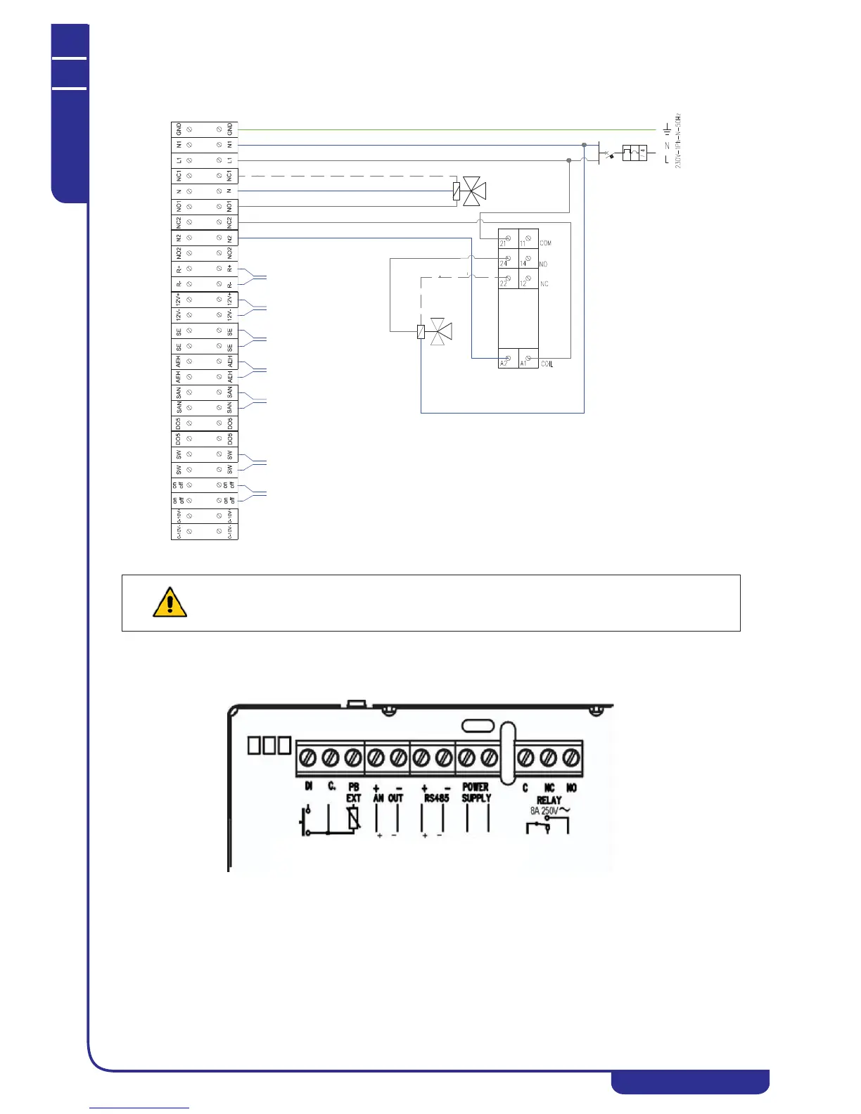
21.8.2 Wiring diagram, configuration with external relay
21.9 Humidity switch connections
Make the following connections between the humidity switch and the minichiller terminal board:
• connect POWER SUPPLY to 12V+ and 12V-
• connect RELAY-C/NC to the two SE terminals
WARNING:
If a double setpoint three-way valve with three point power supply is used in the configuration with external relay, the valve is
live even when the minichiller is OFF or is switched off using the internal circuit breaker. In the event of a system malfunction,
always disconnect the power supply using the external circuit breaker.
3-WAY VALVE
DOMESTIC
3-WAY VALVE
DOUBLE SETPOINT
Connection for valve with 3-point power supply only, system side
Domestic hot water tank side
Fancoil side
* floor side
Relay
Finder
Remote control
serial
Remote control + humidity
switch power supply
Double humidity switch for
NC contact setpoint
Auxiliary heater
220V 5A
Sensor
domestic hot water
Summer/Winter
On/Off
remote
* Connection for valve with 3-point power supply only
11-14 on relay: clean NO contact for fan coil enabling
Maximum permitted resistive load: 8 A
Maximum permitted inductive load: 1.6 A
HOT WATER
Analogue
output
RS485
serial
Power supply
12-24 Vac/dc
Digital
input
External
probe