EasyManua.ls Logo

MTD 110 - User Manual

MTD 110
2 pages
Print Icon
To Next Page IconTo Next Page
Loading...
Model Number
190-110-000
PRINTED IN U.S.A. FORM NO. 770-8358K
GRASS CATCHER
PARTS LIST FOR MODEL 110 GRASS CATCHER
REF. PART
NO. NO.
CODE DESCRIPTION
1 16839B Frame—Lower Ass’y.
2 747-0575 Frame—Upper
3 749-0774 Tube Support
4 764-0271 Grass Bag
5 710-0599 Hex Wash. Hd. TT-Tap
Scr. 1/4-20 x 5" Lg.
6 736-0270 Bell-Wash. 1/4" I.D.
8 747-0870 N Grass Bag Hook
9 710-0751 Hex Bolt 1/4-20 x .62" Lg.*
10 736-0329 L-Wash. 1/4" I.D.*
11 712-3006 Hex Nut 1/4-20 Thd.*
*For faster service obtain standard nuts, bolts and washers locally.
If these items cannot be obtained locally, order by part number
and size as shown on parts list.
HELPFUL OPERATING HINTS
When using the grass catcher, keep the engine
throttle in the “FAST” position so grass discharges
from the chute properly and completely fills the bag.
Always clean the grass catcher bag after use. Grass
remaining in the bag will cause mildew.
If any part of the grass catcher rubs against the
wheels, bend the catcher frame slightly to prevent
wear on the bag.
WARNING: Always stop the engine
before removing the grass catcher. Do
not restart the engine until the grass
catcher has been put back on the mower
in its proper place. Do not make any
adjustment to the grass catcher assem-
bly while the blade is revolving.
NOTE: Under normal usage bag material is subject to
wear and should be checked periodically. Be sure any
replacement bag complies with the mower manufac-
turer’s recommendations. For replacement bags, use
only factory authorized replacement bag No. 764-
0271.
NOTE: Specifications subject to change without
notice or obligation.
Question and Answer IconNeed help?

Do you have a question about the MTD 110 and is the answer not in the manual?

Summary

Grass Catcher Parts List

Helpful Operating Hints and Warnings

Grass Catcher Assembly Instructions

Attach Grass Catcher to Mower

Instructions for attaching the grass catcher to side discharge and 3-in-1 mowers.

Remove Grass Catcher from Mower

Procedure for safely removing the grass catcher from the mower.

Overview

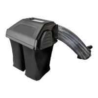
This document is an owner's guide for a grass catcher, specifically Model Number 190-110-000. It provides detailed instructions for assembly, attachment to a mower, removal, and general operating and maintenance tips.

Function Description:

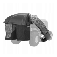
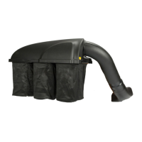
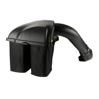
The grass catcher is an accessory designed to collect grass clippings generated by a lawn mower. It attaches to the mower's discharge chute, directing the cut grass into a collection bag, thereby preventing clippings from being scattered across the lawn. This helps maintain a cleaner lawn appearance and can be useful for composting or disposal of clippings. The guide covers its use with both "Side Discharge Mowers" and "3-in-1 Mowers," indicating its versatility across different mower types.

Important Technical Specifications:

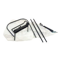
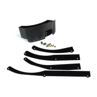
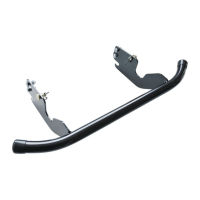
The parts list provides specific component details, which are crucial for identification and replacement. Key components include:

  • Frame-Lower Ass'y. (Part No. 16839B): The foundational structure of the catcher.
  • Frame-Upper (Part No. 747-0575): The upper part of the frame that supports the bag opening.
  • Tube Support (Part No. 749-0774): Connects the upper and lower frame sections.
  • Grass Bag (Part No. 764-0271): The primary collection component. This is a critical replacement part, and the guide emphasizes using only factory-authorized replacement bag No. 764-0271 for compliance with manufacturer recommendations.
  • Various Fasteners: Including Hex Wash. Hd. TT-Tap Scr. 1/4-20 x .5" Lg. (Part No. 710-0599), Bell-Wash. 1/4" I.D. (Part No. 736-0270), Hex Bolt 1/4-20 x .62" Lg. (Part No. 710-0751), L-Wash. 1/4" I.D. (Part No. 736-0329), and Hex Nut 1/4-20 Thd. (Part No. 712-3006). The guide notes that for faster service, standard nuts, bolts, and washers can be obtained locally if they match the specified part numbers and sizes.

The model number for the grass catcher is 190-110-000. The document itself is identified by FORM NO. 770-8358K. Specifications are subject to change without notice or obligation.

Usage Features:

The guide provides comprehensive instructions for using the grass catcher effectively and safely:

  • Assembly:

    1. Attaching Upper Frame to Grass Bag: The upper frame is inserted into the cloth channel of the grass bag, starting from a specific point and working the material around the frame. This process is illustrated in figures A, B, and C.
    2. Inserting Tube Supports: One tube support is placed inside the grass bag, and one end of the upper frame is inserted into it. This step is repeated for the second tube support, as shown in figure D. A soft hammer or mallet may be used for assistance.
    3. Sliding Lower Frame into Tube Supports: The ends of the lower frame assembly are slid into the tube supports (figure E), again with the option of using a soft hammer or mallet.
    4. Securing Bag to Lower Frame: The plastic channels on the bag are worked over the lower frame, starting from the bottom edge, to secure it (figure F).
    5. Final Fastening: A belleville washer (crowned side against the screw head) is placed onto a self-tapping screw, which then goes through an eyelet in the grass bag and is secured to the lower frame.
    6. Closing the Bag: The top of the bag is closed by stretching the loose material over the end of the frame.
  • Attachment to Mower:

    • Side Discharge Mowers: The chute deflector on the mower is raised. The two outside tabs on the grass catcher frame are slipped underneath the hinge pin on the chute deflector (figure G). Releasing the chute deflector locks the catcher in position.
    • "3-in-1" Mowers: The grass bag hook is positioned against the grass catcher frame and secured with a 5/8" long hex bolt, lock washer, and hex nut (figure H). The mulching plug on the mower is lifted, and the grass bag is slid into position so its hook is inside the two hooks on the mulching plug adapter plate (figure I). The mulching plug is then lowered into operating position.
  • Removal from Mower: The chute deflector (or mulching plug) is lifted, and the grass catcher is removed from the adapter plate. The deflector/plug is then carefully lowered.

  • Operating Hints:

    • Engine Throttle: Keep the engine throttle in the "FAST" position to ensure proper and complete discharge of grass into the bag.
    • Bag Capacity: Empty the grass through the top opening of the catcher. Ensure the bag is closed before reattaching it to the mower.
  • Safety Warnings:

    • Engine Stop: Always stop the engine before removing the grass catcher. Do not restart the engine until the grass catcher is properly reinstalled.
    • No Adjustments While Blade Revolves: Never make any adjustments to the grass catcher assembly while the blade is revolving.
    • Do Not Operate with Bag Open: Never operate the mower with the bag open.

Maintenance Features:

  • Cleaning: Always clean the grass catcher bag after use. Grass remaining in the bag can cause mildew.
  • Frame Alignment: If any part of the grass catcher rubs against the wheels, bend the catcher frame slightly to prevent wear on the bag.
  • Bag Material Inspection: The bag material is subject to wear under normal usage and should be checked periodically.
  • Replacement Parts: For replacement bags, it is crucial to use only factory-authorized replacement bag No. 764-0271 to ensure compliance with the mower manufacturer's recommendations. This is highlighted as a "NOTE" to emphasize its importance.
  • Fasteners: For faster service, standard nuts, bolts, and washers can be obtained locally if they match the specified part numbers and sizes. Otherwise, they should be ordered by part number.

The document is well-structured with clear illustrations and step-by-step instructions, making it user-friendly for assembly, operation, and basic maintenance of the grass catcher.

MTD 110 Specifications

General IconGeneral
BrandMTD
Model110
CategoryLawn Mower Accessories
LanguageEnglish

Related product manuals