Adjustments
WARNING
The cable must be
routed propedyto
avoid contact with
all sharp edges and
hotsurfaces. Such
contacts damage the
cable and render the
controlsinoperative.
iMPORTANT
The blade control
handle is a safety
device. Never at-
tempt to bypass its
operations.
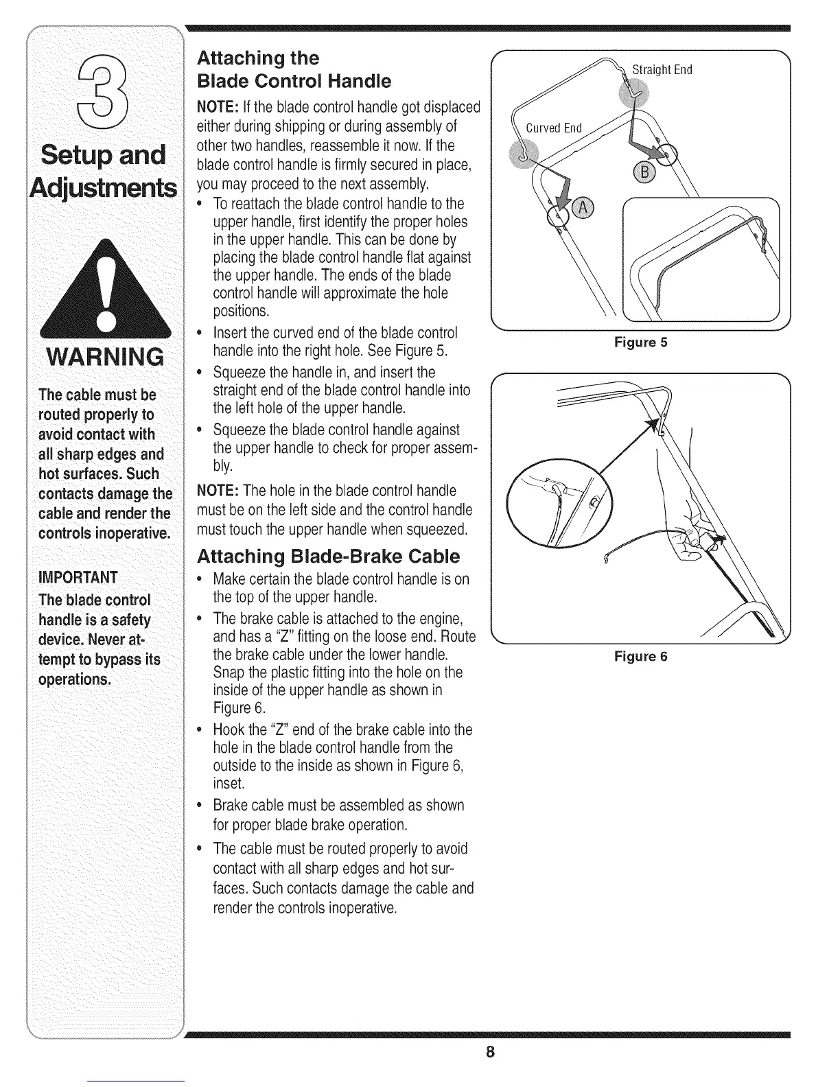
Attaching the
Blade Control Handle
NOTE: If the bladecontrol handle got displaced
either during shipping or during assemblyof
other two handles, reassembleit now. Ifthe
bladecontrol handle is firmly secured in place,
you may proceedto the next assembly.
,, Toreattachthe bladecontrol handleto the
upper handle,first identify the proper holes
in the upper handle.This can be done by
placingthe blade control handle flat against
the upperhandle. The ends of the blade
control handle will approximatethe hole
positions.
• insertthe curved end of the blade control
handle into the right hole.See Figure 5.
,, Squeezethe handle in, and insertthe
straight end of the blade control handle into
the left hole of the upper handle.
,, Squeezethe blade control handle against
the upperhandle to checkfor proper assem-
bly.
NOTE: The hole in the blade control handle
must be on the left side and the control handle
must touchthe upper handle when squeezed.
Attaching Blade-Brake Cable
• Makecertain the blade control handle is on
the top of the upper handle.
• The brakecable is attached to the engine,
and has a "Z" fitting on the loose end. Route
the brakecable underthe lowerhandle.
Snapthe plastic fitting into the hole on the
inside of the upperhandle as shown in
Figure6.
• Hookthe "Z" end of the brake cable into the
hole in the bladecontrol handle from the
outside to the inside as shown in Figure 6,
inset.
• Brake cable must beassembled as shown
for proper blade brakeoperation.
• The cable must be routed properlyto avoid
contact with all sharp edges and hot sur-
faces. Such contacts damage the cable and
render the controls inoperative.
Straight End
CurvedEnd
Figure 5
Figure 6
8
 Loading...