7
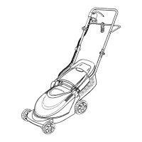
SECTION 3: ASSEMBLING YOUR LAWN MOWER
Loose Parts in Carton
• Grass Catcher Assembly.
• Owner’s Manual (not shown).
• Hardware Pack.
• Upper and Lower Handle w/ Guide Rod.
• Wheel Assemblies (4)
Tools Required
• Phillips head screwdriver.
• Adjustable wrench, a wrench set or socket set.
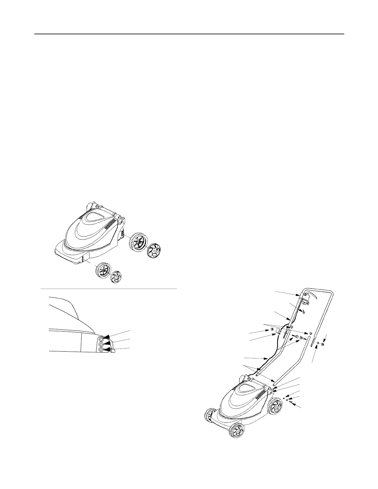
Attaching Wheels
The wheels for your mower will not require tools to
install. Notice that there are two large wheel assemblies
and two smaller wheel assemblies. The large wheels fit
on the rear and the small wheels are for the front of the
mower. To install the wheels:
Figure 1
• Rest the mower on its side or place supporting
blocks under one side of the mower.
• Refer to Figure 1 and insert the hubcap assembly
through the wheel and thread the complete
assembly into the desired height adjustment
position by hand.
NOTE: It is recommended to use the highest cutting
position initially to avoid scalping of the grass.
• By putting fingers into the grooves in the hubcap
assembly, tighten firmly.
• Repeat this step for all wheels, being certain that all
four wheels are in the same height position for an
even cut. Refer to Figure 1 for cutting height
positions.
• Also, be certain the smaller front wheels and the
larger rear wheels are mounted correctly to the
front and rear of the mower as shown in Figure 1.
Assembling Handle
Installing the Lower Handles
• Insert long end of the lower handle into the handle
base. Make certain the small hole in the end of the
handle is lined up with the hole in handle base.
• Using one of the two longer self tapping screws
from the hardware pack, insert the screw through
the tooth washer, flat washer, and the handle cap
as shown in Figure 2.
• Align the handle cap so it rests flush against the
handle base, and tighten the screw into the lower
handle using a phillips screwdriver.
• Repeat this step for the remaining lower handle.
• Once both lower handles are installed, insert the
lower handle plugs into the upper ends of the lower
handles as shown in Figure 2.
Installing the Upper Handle
• Standing behind the lawnmower with the upper
handle, make certain the two holes that will hold the
blade / motor control are on the right hand side.
See Figure 2 for proper alignment of upper handle.
Figure 2
Right Front View
Cutting Height Positions
Low
Medium
High
Front Wheel
Rear Wheel
Hubcap Assembly
Hubcap Assembly
Lower Handles
Upper Handle
Lower Handle Plugs
Blade / Motor Control
Flat Washer
Tooth Washer
Self Tapping
Washer Head Screw
Hex Bolt
Cord Insulator
Hex Nut
Lock Washer
Hex Nut
Handle Cap
Handle Base
Screw
Power Cord