ASSEMBLY & INSTALLATION
7
NOTE: It might be easier during the mounting stage to leave this hardware only finger tight
to facilitate lining up the hitch hole for the clevis pin. You will be instructed to tighten this
hardware later in this manual.
NOTE: The holes closest to the mounting
hooks are to be used for all 700 series model
tractors, see Figure 4 (1), while the
two holes closest to the cross mount are
for all other models, see Figure 4 (2). The
hitch support bracket will need to be
flipped to enable alignment of the proper
holes depending on the model of tractor
this bagger is being installed on.
Mounting Assembly on 700
Series Tractors
1. Place the hooked ends of the
mounting assembly over the
shoulder bolts on the mounting
brackets previously installed on the
tractor and line up the hitch
support bracket center hole with
the hole on the tractor’s hitch. See
Figure 5.
2. Install the clevis pin (711-0309A)
from hardware pack 689-02364
into the tractor’s hitch and secure
with a cotter pin (714-0117). See
Figure 6.
3. Replace two previously removed
clevis pins through the mounting
assembly and secure to the 700
series mounting brackets installed
earlier with cotter pins provided in
the hardware pack. See Figure 6.
NOTE: The clevis pin can be fed down
through the hitch plate and secured
underneath with the cotter pin, or it may
be easier to feed the clevis pin up through the hitch plate hole and secure with the cotter pin
on the topside. Insert the cotter pin into the top hole, closest to the head of the pin. You may
need to push up on the pin to make the hole accessible.
IMPORTANT: If you decided to leave the hitch support only finger tight during the assembly
process, tighten all of the hardware securely at this time.
Mount Assembly on All Other Tractors
1. Place the hooked ends of the
mounting assembly over the
shoulder bolts on the back of the
tractor frame and line up the hitch
support bracket center hole with
the hole on the tractor’s hitch. See
Figure 7.
For All Other Models
Knob Hole Position
Figure 4 (2)
Figure 5
Align hole on bracket
with hole on tractor
Figure 6
Figure 7
Align hole on
bracket with hole
on tractor
Figure 8
2. Install the clevis pin (710-0309A)
from hardware pack 689-02364
into the tractor’s hitch and secure
with a cotter pin (714-0117).
See Figure 8.
NOTE: The clevis pin can be fed down
through the hitch plate and secured
underneath with the cotter pin, or it may
be easier to feed the clevis pin up through
the hitch plate hole and secure with the
cotter pin on the topside. Insert the cotter
pin into the top hole, closest to the head
of the pin. You may need to push up on the pin to make the hole accessible.
IMPORTANT: If you decided to leave the hitch support only finger tight during the assembly
process, tighten all of the hardware securely at this time.
Mount the Vertical
Support Bracket
1. Install the vertical support bracket
onto the mounting assembly on the
tractor by hooking it over the cross
mounting bracket. See Figure 9.
2. Align the vertical support bracket
with the hole that best suits the
deck size of your tractor.
3. Secure the bag support assembly to
the mounting assembly using a
carriage bolt (710-0276) and wing
knob (720-04122) from hardware
pack 689-02364. See Figure 10.
NOTE: Hole “A” is suggested for 38”
decks, Hole “B” is suggested for 42” decks
and Hole “C” is suggested for 46” decks.
Some kits may contain plates with the
deck size suggestions instead of letters.
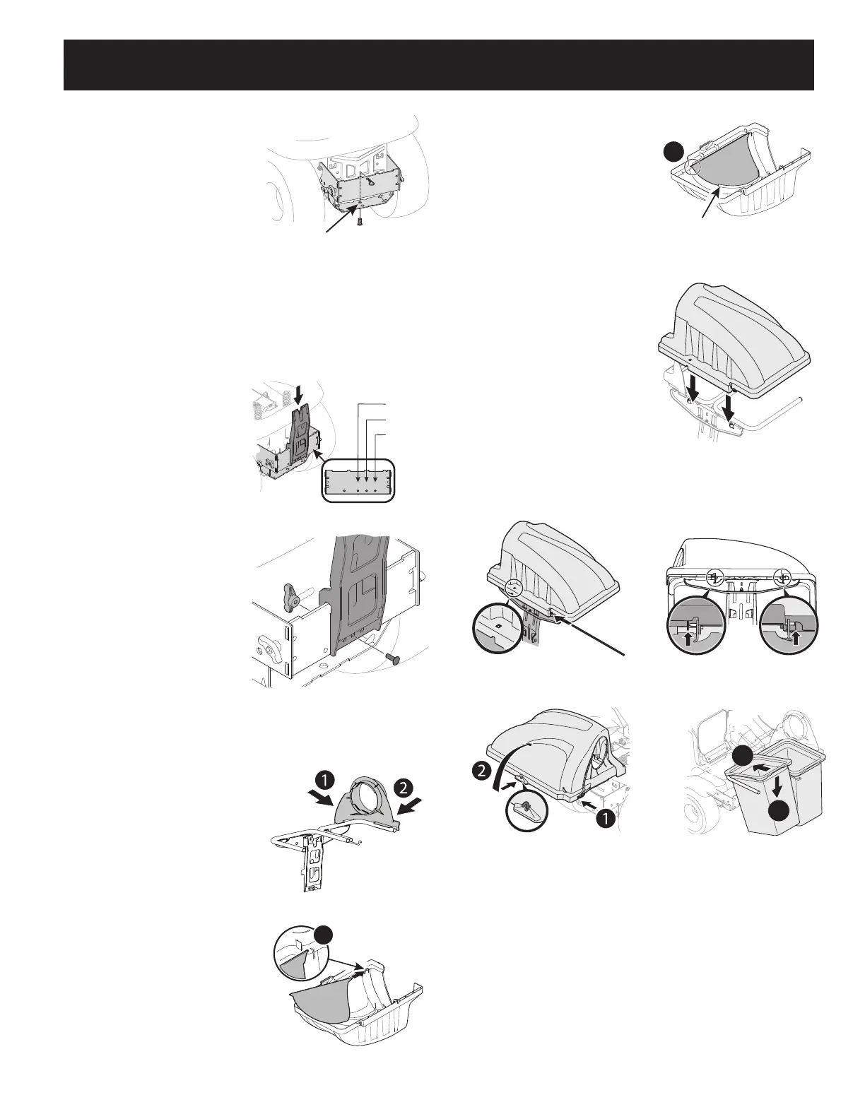
Install Top Bagger Components
With the mounting brackets assembled and
in place on the tractor, follow these steps to
assemble the remaining bagger components.
1. Snap the upper chute support (731-17091)
in place by first clipping the side portion
onto the hanger assembly rail (1), as
shown in Figure 8.
2. Snap the front side of the upper chute
support to the rail (2), as shown in
Figure 8.
3. If not already done so by the factory,
install the screen (731-06504) into
the bagger cover (631-04292) by first
inserting the end closest to the side with
the cut-out (1) into the mounting hole,
as in Figure 9..
38” Deck
42” Deck
46” Deck
A B C
Figure 9
Figure 10
Figure 11
4. Make sure to feed the screen under the
lip. Clip in the other side by pushing the
screen into the provided cut-out (2). See
Figure 10.
5. Install the bagger cover onto the hanger
assembly, as seen in Figure 11. The cover
goes inside the two mounting tabs.
6. Slide the hinge pin (711-04988) into
the hole located on the mounting tab,
as shown in Figure 12. Use the cut-out
window (see inset in Figure 12) to line
up the hinge pin on the other side and
push pin all the way in until it reaches the
end-stop. At this point the pin clips into
place and is secured by a tab in the bagger
cover. See Figure 13.
7. Open bagger cover by pushing in on the
rear, right-side tab with your right hand
(1), and lifting the cover with your left
hand in the center rear of
the bagger cover (2) as shown in Figure 14.
8. Install both grass bag assemblies (664-
05104) onto the hanger assembly rails by
inserting the front edge in first (1), and then setting the back edge down until it fits into
the assembly (2), as shown in Figure 15.
1
Figure 12
Make sure screen sits
under the cover’s lip
2
Figure 13
Figure 14
Figure 15
Figure 16
Figure 17
2
1
Figure 18

 Loading...