15Section 4 — ASSembly & inStAllAtion
Install The Counter Weight
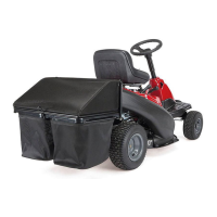
The front weight kit is designed for use with all RZT-L (Lap
Bar) Residential Zero-turn models. The front weight kit is NOT
designed nor required for use with all RZT-S (Steering Wheel)
Residential Zero-turn models.
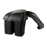
WARNING: This front-weight kit is required when
operating any compatible lap bar RZT-L models
equipped with a grass collector. Failure to install this
kit may result in serious injury or death.
WARNING: Before beginning installation, place
the RZT-L on a firm and level surface, set the parking
brake, place the PTO in the disengaged (OFF)
position, stop the motor and remove the ignition
key to prevent unintended starting.
Note: The front weight kit is not utilized on the RZT-S (Steering
Wheel) Residential Zero Turn units. Do not attempt to mount it
on RZT-S models, as it will not fit.
RZT models are available with two different front-end styles.
Identify your RZT using the images in the following instructions
and follow the applicable steps.
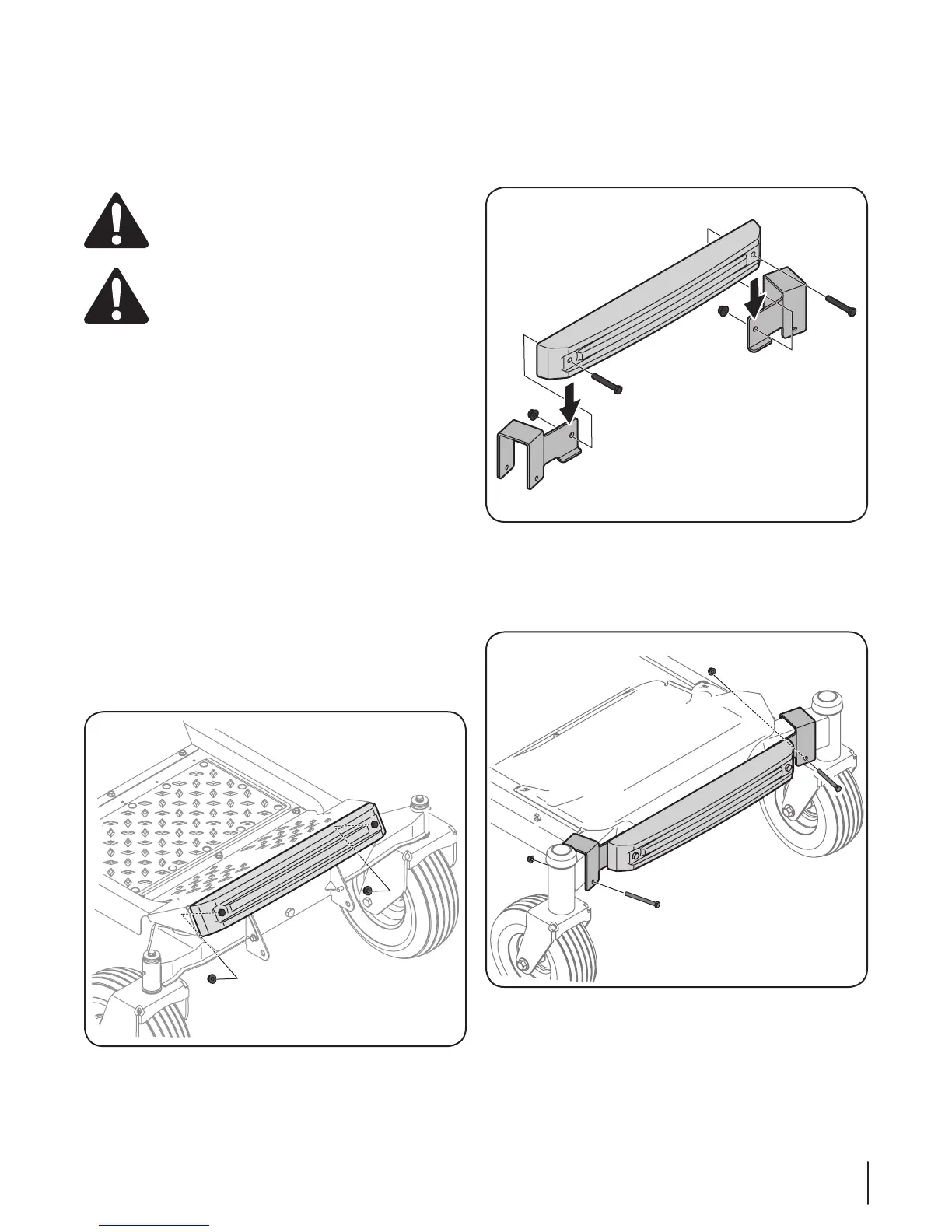
RZT Models with a Pivoting Front Axle
Note: Having a second person assist you by holding the weight
bar in place will ease in completing the following steps.
1. Insert the two 3 1⁄4-inch (710-3056) screws from hardware
pack 689-00325, into the weight bar.
2. Position the weight bar onto the foot rest and secure it in
place with two 3⁄” flange nuts (712-04065) from the same
hardware pack. See Figure 4-25.
Note: To hold and retain nut for tightening, it may
be necessary to insert the nut into the box end of a
combination wrench and slide up through the opening in
the floorboard.
Figure 4-25
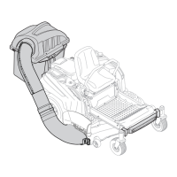
RZT Models with a Fixed Front Axle
1. Attach the left mounting bracket and the right mounting
bracket to the weight bar using two 2⁄-inch screws (710-
0859), and ⁄” flange nuts (712-04065) from hardware pack
689-00325. See Figure 4-26.
Figure 4-26
2. Attach the weight bar assembly to the front axle with a 3
1⁄4-inch (710-3056) screw and (712-04063) flange nut from
hardware pack 689-00325 on the left side. Repeat on the
right side. Do not fully tighten at this time. See Figure 4-27.
Figure 4-27
3. Visually center the weight bar assembly on the tractor
and tighten the hardware installed in step 2 to secure the
brackets to the front axle.