SECTION2: ASSEMBLINGYOURLOGSPLITTER
UnpackingfromCrate
• Pry top, sides, and ends off the crate. Set panels
aside to avoid tire puncture or personal injury.
• Remove and discard plastic bag that covers unit.
• Remove any loose parts if included with unit (i.e.,
operator's manual, etc.)
• Cut and remove straps which secure parts to
bottom of crate. Unbolt any remaining parts which
may be bolted to the bottom of the crate.
WARNING" Use extreme caution unpackingthis machine. Some components are very
heavy and will require additional people or
mechanical handling equipment.
LoosePartsIn Carton
• Tongue assembly
NOTE: Reference to right or left hand side of the log
splitter is observed from the operating position.
NOTE: Log splitter features vary by model NOT all
components discussed in this manual are standard
equipment.
AssemblingtheTongue
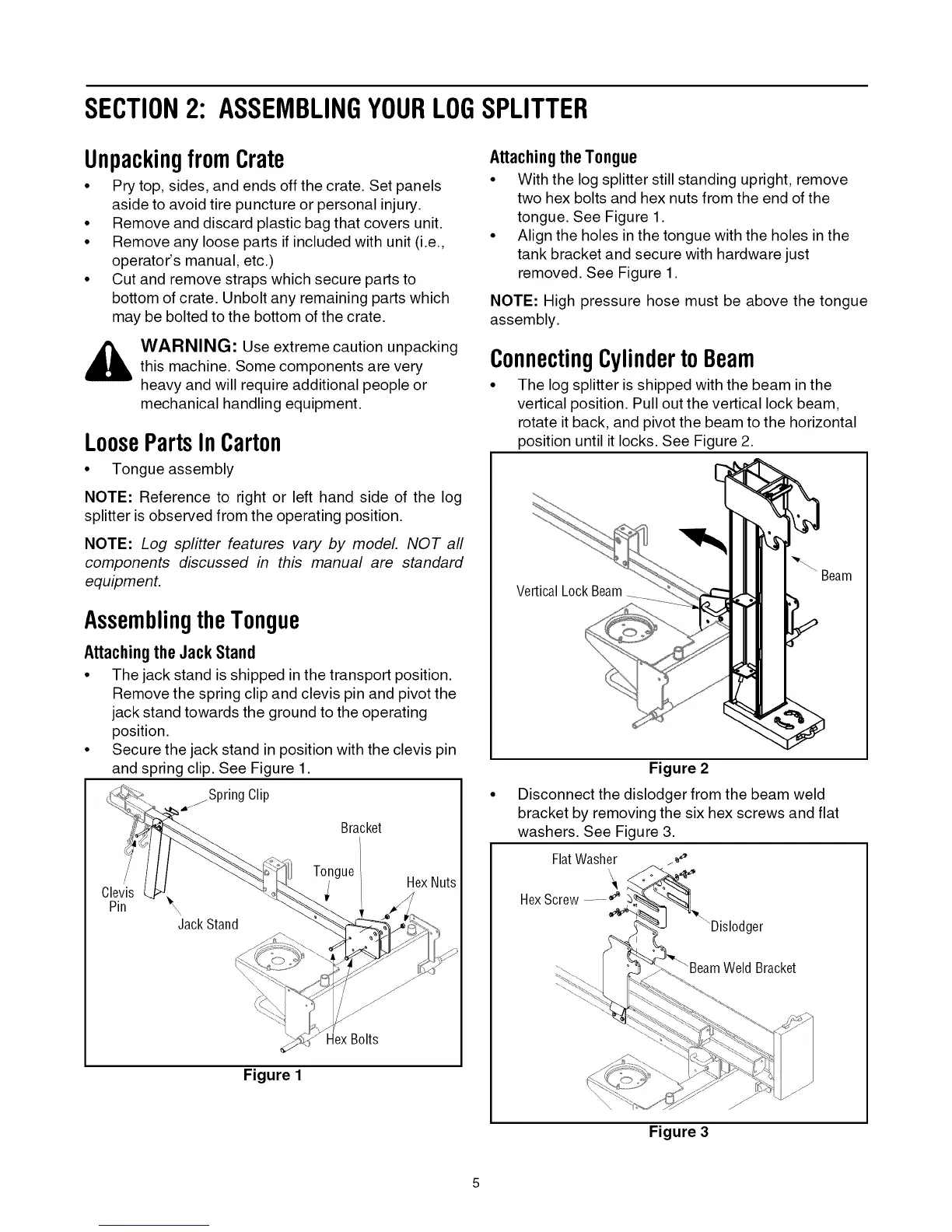
Attachingthe JackStand
• The jack stand is shipped in the transport position.
Remove the spring clip and clevis pin and pivot the
jack stand towards the ground to the operating
position.
• Secure the jack stand in position with the clevis pin
and spring clip. See Figure 1.
Spring Clip
Bracket
Pin
JackStand
Tongue
Hex Nuts
HexBolts
Figure 1
AttachingtheTongue
• With the log splitter still standing upright, remove
two hex bolts and hex nuts from the end of the
tongue. See Figure 1.
• Align the holes in the tongue with the holes in the
tank bracket and secure with hardware just
removed. See Figure 1.
NOTE: High pressure hose must be above the tongue
assembly.
ConnectingCylindertoBeam
• The log splitter is shipped with the beam in the
vertical position. Pull out the vertical lock beam,
rotate it back, and pivot the beam to the horizontal
position until it locks. See Figure 2.
Vertical Lock Beam
Beam
Figure 2
Disconnect the dislodger from the beam weld
bracket by removing the six hex screws and flat
washers. See Figure 3.
FlatWasher
*I
HexScrew......."_
ger
Weld Bracket
Figure 3