PARKING BRAKE
The speed control lever is used to set the parking
brake. To set the parking brake, depress the clutch-
brake pedal. Move the speed control lever out of the
notches to the parking brake position. Release the
speed control lever and the clutch-brake pedal.
To release the parking brake, depress the clutch-
brake pedal and move the speed control lever out of
the notches to the desired position, Release the
speed control lever and the clutch-brake pedal.
NOTE: The parking brake must be set if the
operator leaves the seat with the engine running
INTERLOCKS (Not Shown)
Interlock safety switches are located by the clutch-
brake pedal, the lift lever, the shift lever and under the
seat.
Before the engine will start, the clutch-brake pedal
must be depressed all the way and the lift lever must
be in the BLADES STOP position.
Before the unit can be shifted into reverse or if the
operator leaves the seat, the lift lever must be in the
BLADES STOP position.
INDICATOR LIGHTS (Optional)
If your unit is equipped with indicator lights, two or
three indicator lights are located in the dash panel. If
a light illuminates when attempting to start the unit,
proceed as follows.
CLUTCH--Depress the clutch pedal,
PTO--Place lift lever in the BLADES STOP position,
OIL (Vanguard Twin and Intek twin Engines Only)-
Check the crankcase oil level, and add oil as
required.
CUTTING CONTROLS
A. LIFT LEVER
The lift lever is used to raise and lower the cutting
deck and to engage and disengage the blades. Pull-
ing it all the way back and locking it disengages the
blades.
NOTE: The lift lever must be in the BLADES
STOP position when starting the engine, when
shifting into reverse and ff the operator leaves the
seat. See Figure 14.
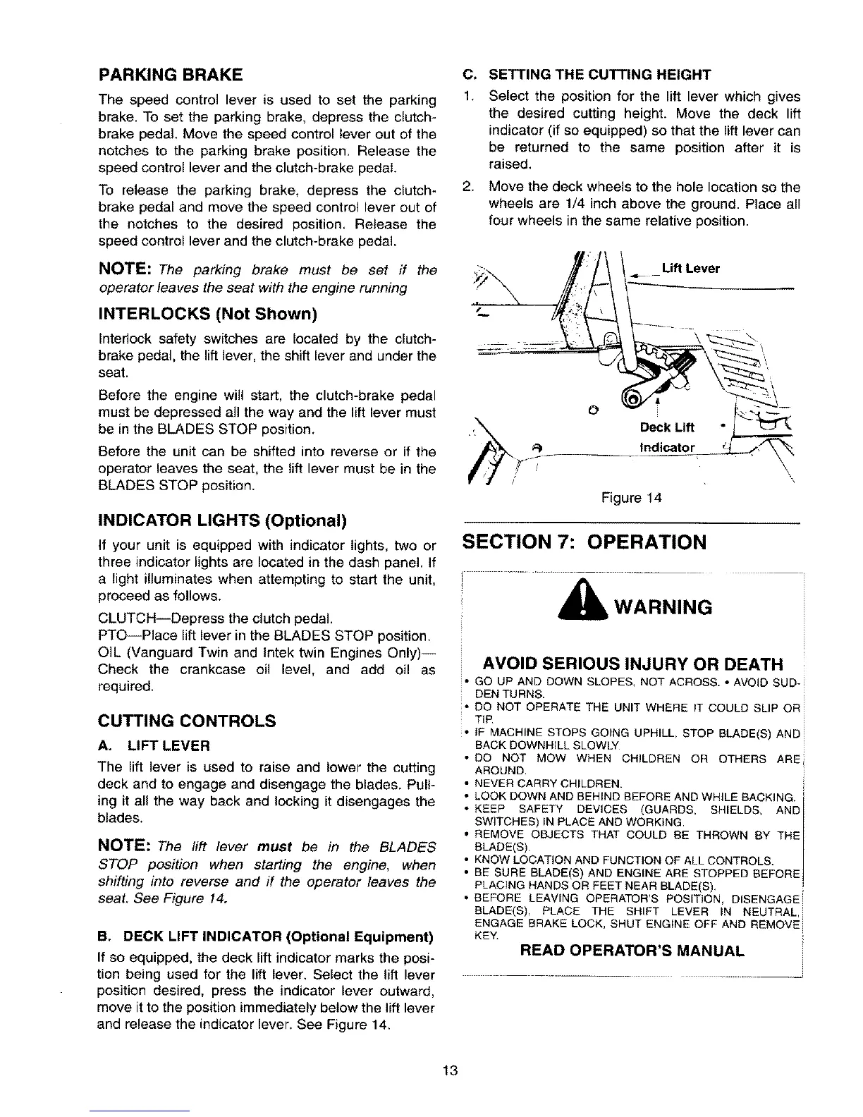
B. DECK LIFT INDICATOR (Optional Equipment)
If so equipped, the deck lift indicator marks the posi-
tion being used for the lift lever. Select the lift lever
position desired, press the indicator lever outward,
move it to the position immediately below the lift lever
and release the indicator lever. See Figure 14_
C.
1.
2.
SETTING THE CUTTING HEIGHT
Select the position for the lift lever which gives
the desired cutting height. Move the deck lift
indicator (if so equipped) so that the lift lever can
be returned to the same position after it is
raised,
Move the deck wheels to the hole location so the
wheels are 1/4 inch above the ground. Place all
four wheels in the same relative position.
Lift Lever
I
O
Deck Lift
Indicator
Figure 14
\
SECTION 7: OPERATION
WARNING
AVOID SERIOUS INJURY OR DEATH
• GO UP AND DOWN SLOPES_ NOT ACROSS. * AVOID SUD-
DEN TURNS.
• DO NOT OPERATE THE UNIT WHERE IT COULD SLIP OR
TiP
• IF MACHINE STOPS GOING UPHILL, STOP BLADE(S) AND
BACK DOWNHILL SLOWLY
• DO NOT MOW WHEN CHILDREN OR OTHERS ARE
AROUND.
• NEVER CARRY CHILDREN.
° LOOK DOWN AND BEHIND BEFORE AND WHILE BACKING. i
F
• KEEP SAFETY DEVICES (GUARDS, SHIELDS, ANDI
• SWITCHES) IN PLACE AND WORKING. I
REMOVE OBJECTS THAT COULD BE THROWN BY THE I
BLADE(S) I
• KNOW LOCATION AND FUNCTION OF ALL CONTROLS.
• BE SURE BLADE(S) AND ENG NE ARE STOPPED BEFORE
PLACING HANDS OR FEET NEAR BLADE(S).
• BEFORE LEAVING OPERATOR'S POSITION, DISENGAGE
BLADE(S), PLACE THE SHIFT LEVER IN NEUTRAL,
ENGAGE BRAKE LOCK, SHUT ENGINE OFF AND REMOVE
KEY.
READ OPERATOR'S MANUAL
13
 Loading...