Withtheengineoff,placetheliftleverinthehighest
cuttingposition(firstposition).Removethecotterpin
andflatwasherwhichsecurethedisengagementrod
to the stabilizershaft assembly.See Figure16.
Shortentherodbythreadingit in untiltheferruleis
againstthebackoftheslotintheliftshaftassembly,
andthe rod linesup withthe holein thestabilizer
shaft,Formorebelttensionthedisengagementrod
mustbe lengthened.To decreasebelttensionthe
disengagementrodmustbeshortened.
Checktheadjustmentbyplacingthelift leverin the
BLADESSTOPposition.Thedeckshouldmoveup
and forward,allowingthe belt to becomeloose.
Startandtestfordisengagement,Repeatprocedure
asnecessary.
Stabilizer Shaft Disengagement
Assembly / Rod
Hairpin Clip _38'' Decks
Stabilizer Shaft
Assembly
I //\,h
Disengagement
Rod
Stabilizer
Flat Washer
Hairpin Clip _
42 and
46 Decks
Figure 16
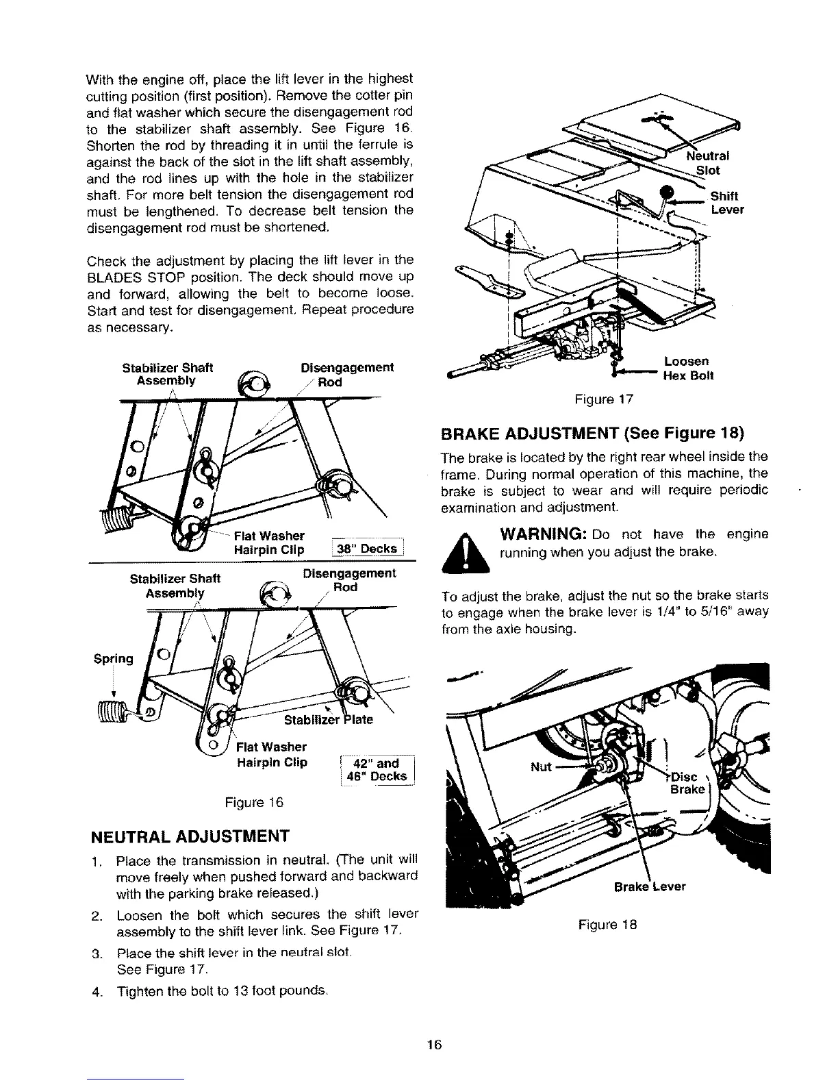
NEUTRAL ADJUSTMENT
1. Place the transmission in neutral. (The unit will
move freely when pushed forward and backward
with the parking brake released.)
2. Loosen the bolt which secures the shift lever
assembly to the shift lever link. See Figure 17.
3. Place the shift lever in the neutral slot.
See Figure 17.
4. Tighten the bolt to 13 foot pounds,
Neutral
Slot
Shift
Lever
Loosen
Hex Bolt
Figure 17
BRAKE ADJUSTMENT (See Figure 18)
The brake is located by the right rear wheel inside the
frame. During normal operation of this machine, the
brake is subject to wear and wilt require periodic
examination and adjustment.
WARNING: Do not have the engine
running when you adjust the brake,
To adjust the brake, adjust the nut so the brake starts
to engage when the brake lever is 1/4" to 5/16" away
from the axle housing.
_Lever
Figure 18
16
 Loading...