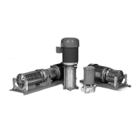
Refer to Figure 4-11 for reference to
the numbered parts in the reassembly
1. Install the guide rods. Thread the
four (4) Guide Rods (#18) into the
motor or bearing frame face. It
is not necessary to turn them in
completely or tighten. About half
of the thread length should be
2. The Seat Stationary Seat (#125)
must be installed in the Inlet Cover
(#1 or #1IN) before the cover is
installed on the motor. To install
a. Place the inlet cover face up
b. Carefully press the seat,
seat cavity of the inlet cover.
of the seat easier, apply a
thin coating of glycol base
lubricant to the elastomer
portion of the seat prior to
installation. Care must be
taken not to damage the seat
usually suffi cient to install the
3. Install the Inlet Cover (#1 or 1IN).
a. Make sure the Drive Collar
(#14) is positioned on the
b. While holding the inlet cover
with the inlet port 180° from
the motor conduit box (or
vertically on horizontal units),
slide the cover over the guide
c. Slide the inlet cover back until
the feet are resting against
the face. Light tapping may
be necessary to seat the inlet
cover in the proper position.
d. Install one (1) “O” Ring (#8)
on each of the four guide
rods. This will help hold the
bracket in place during the
remainder of the assembly
4. On inducer pumps (L50 Series)
install one Snap Ring (#14A) in
the groove nearest the drive end
of the Shaft (#17), and slide the
Seal Driver (#88) on the shaft.
5. Install the Shaft (#17) and Seal
Rotating Element (#12) as a unit.
a. Lubricate the small end of
the shaft and the rotating
assembly between the thumb
hands, slide the assembly
over the shaft until the spring
shoulder. Refer to Figure
c. The element must slide freely
up and down the shaft. It is
necessary to maintain some
element because the spring
tension could dislodge the
seal portion of the element.
d. Install a Drive Key (#23A)
in the motor shaft before
installing the shaft and seal
e. Align the keyway and slide
motor shaft. Push the shaft in
until it comes in contact with
f. Position the drive collar over
the shaft end and push the
g. While maintaining inward
pressure on the shaft with
one hand, line up the Collar
Setscrews (#15) with the key
in the motor shaft, placing
one setscrew on each side of
h. Using the hex wrench, tighten
should remain in position.
cavity for proper impeller
6. It is recommended that the
assembly be placed vertically
on the motor or pedestal end for
further assembly. Blocks can be
For standard (M50 Series) pumps, skip
7. For inducer (L50 series), install the
Inducer Impeller (#11IN). Refer
to the L50 Inducer Stage Inset in
a. Install an Impeller Key (#23)
in the shaft by the drive collar.
b. Slide the inducer impeller on
the shaft with the eye facing
c. Install the other Snap Ring
(#14A) on the shaft at the hub
8. Install the Diffuser Ring (#9IN).
a. Place an “O”Ring (#7) on
the raised step in the diffuser
ring. You will need to stretch
the “O”ring slightly to do so.
b. Coat the “O”ring and the lip
inside the inlet cover with a
small amount of glycol base
c. With the “O”ring facing the
inlet cover, slide the diffuser
ring onto the guide rods so
that it fi ts over the inducer
the “O” ring fi ts inside the lip
in the inlet cover. Refer to
9. Installation of the First Stage
a. Place the small “O”Ring
(#7A) in to the groove in the
hub of the inlet cover (#1
- 1IN) or Diffuser Ring (#9IN)
b. Install an Impeller Key (#23)
c. Place an “O” ring (#7) on the
raised step in the channel


 To Next Page
 Loading...