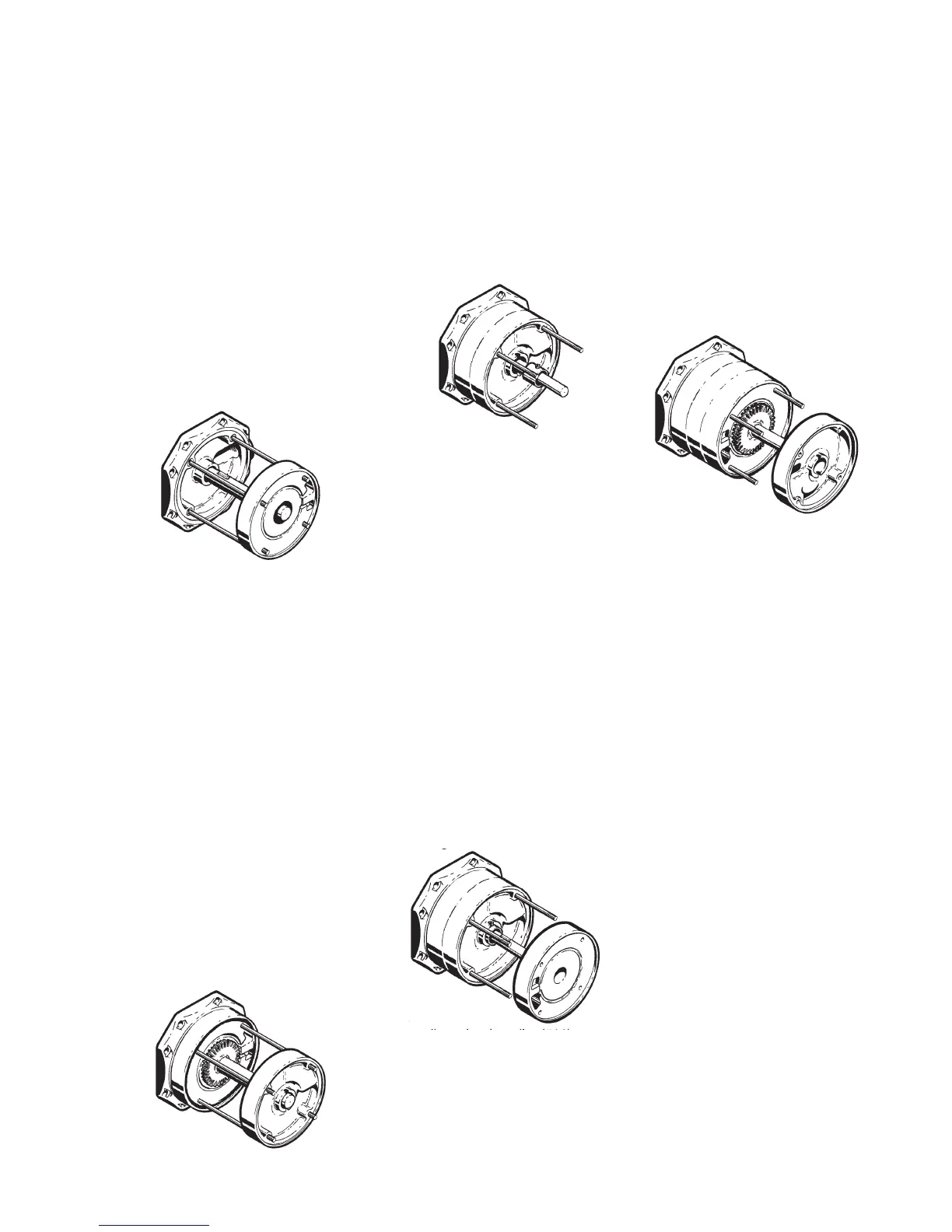
This completes one stage; a stage
consists of one Left Hand Channel
Ring (#10), a Right Hand Channel Ring
(#9), and an Impeller (#11) between
them. Refer to Figure 4-11.
13. Install another Left Hand Channel
a. Install an Impeller Key (#23)
b. Place an “O”Ring (#7) on the
raised step in the channel
ring. Lubricate the “O”ring
and inside lip in previous
c. Slide the channel ring
into place with the water
channel facing up. This time,
however, orient the large inlet
opening on the side opposite
of the pump inlet. Refer to
ring. You will need to stretch
the “O” ring slightly to do so.
d. Coat the “O” ring and lip in
inlet cover (or diffuser ring)
with a small amount of glycol
e. With the “O”ring facing the
motor end, slide the channel
ring (#10) onto the guide rods
with the water channel facing
up. The large inlet opening
should be on the same side
as the pump inlet. Refer to
fi gure 4-15. Push on fi rmly
until the “O”ring fi ts inside
the lip in the inlet cover (or
diffuser ring). Refer to Figure
on fi rmly until the “O” ring fi ts
inside the lip in the left hand
channel ring. Refer to Figure
12. Slide an Interstage Bushing (#16)
onto the shaft. The bushing
should be oriented such that the
end with the screw is furthest from
the motor and the screw head fi ts
into the slot in the right channel
ring. Refer to Figure 4-17.
a. Place an “O”Ring (#7) on the
raised step in the channel
b. Slide the channel ring onto
the guide rods with the water
channel facing down towards
outlet opening should be on
the opposite side from the
pump inlet. Refer to Figure
4-19. Push on fi rmly until the
“O”ring fi ts inside the lip in the
previously installed channel
10. Slide an Impeller (#11) on the
shaft and over the drive key, with
the impeller hub facing the motor.
11. Install a Right Hand Channel Ring
a. Place an “O”Ring (#7) on the
raised step in the channel
ring. You will need to stretch
the “O”ring slightly to do so.
b. Coat the “O”ring and lip in
previous ring with a small
c. With the “O”ring facing the
left hand channel ring, slide
the channel ring onto the
guide rods. The small outlet
same side as the pump inlet.
Refer to Figure 4-16. Push
14. Install another Impeller (#11),
14. Install another Impeller (#11),
remembering to point the impeller
15. Install another Right Hand
16. Slide an Interstage Bushing (#16)
onto the shaft. The bushing
should be oriented such that the
end with the screw is furthest from
the motor and the screw head fi ts
into the slot in the right channel
ring. Refer to Figure 4-17.
Continue installing stages depending
on how many stages are in the
pump by repeating steps 9 through
sets to balance radial loads. The
odd numbered stages should have
openings on the same side as the
pump inlet, as described in the fi rst
stage installation (steps 9 through 12).
The even numbered stages should
have their openings on the opposite
side from the pump inlet, as indicated
(in steps 13 through 16) for the second
17. Install one (1) “O”Ring (#8) on
each of the four Guide Rods (#18)
18. Replace the Plain Bearing
(#87) in the Outlet Cover (#2),
if it has been removed. If not,
proceed to step 19. The bearing
is an interference fi t and the
Outlet Cover must be heated
to approximately 300°F before
pressing in. Allow the Outlet
Cover to cool before proceeding


 To Next Page
 Loading...