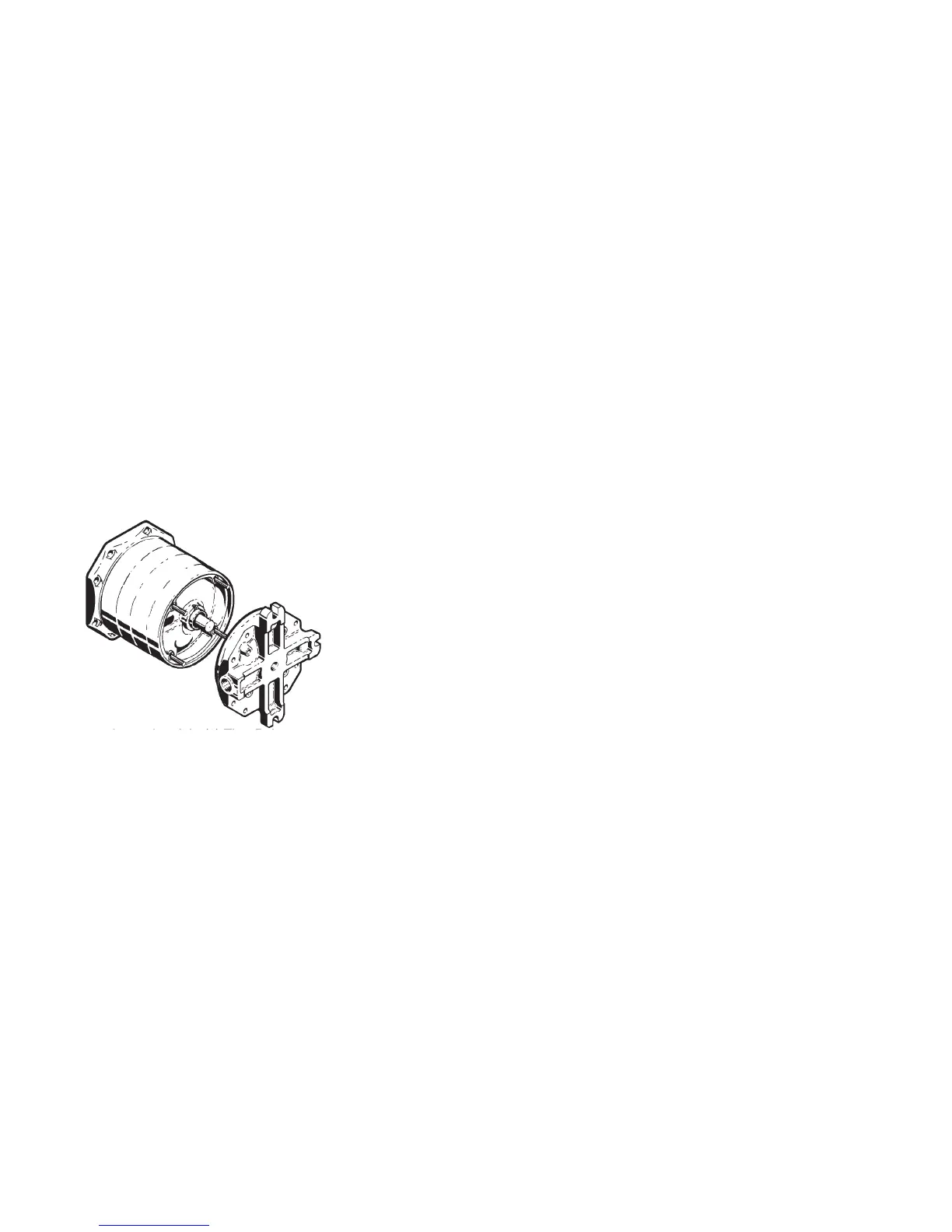
19. Install the Outlet Cover
a. Place an “O”Ring (#7) on
the raised step in the outlet
stretch the “O”Ring slightly to
b. Coat the “O”Ring and lip in
the last right channel ring (#9)
with a small amount of glycol
c. With the “O”Ring facing the
last channel ring, slide the
Outlet Cover (#2) over the
Guide Rods. The outlet port
should be oriented 180° from
the inlet port on close coupled
units. The outlet port should
be oriented on the same side
as the inlet port on horizontal
units. Push on fi rmly until
the “O”Ring fi ts inside the lip
of the channel ring. Refer to
Proceed to Section 4I Testing and
4H Reassembly Multistage on C30
Motors / P30 Bearing Frames
All parts should be visually inspected
and cleaned or replaced as outlined in
The following tools and equipment are
needed for reassembly of C30 / P30
1. Soft plastic or wooden mallet.
2. Two 9/16” wrenches or sockets.
5. Adjustable spanner wrench.
6. Thin blade screwdriver.
8. Cealube G or similar glycol
base lubricant. (DO NOT use
9. 7/16” wrench or socket
Refer to Figures 4-12 for reference to
the numbered parts in the reassembly
1. Using an arbor press, install
the Bearing (#24) on the Motor
Adapter Shaft or Bearing Frame
2. Install Bearing Lockwasher (#39)
on the shaft, aligning internal tang
into the keyway in the shaft, and
with the external tangs facing
away from the bearing. Install
Bearing Locknut (#38) on shaft,
with beveled side facing the
bearing. Tighten snuggly, using
a drift punch if necessary, until
a slot lines up with a tang on the
lockwasher. Using a thin blade
screwdriver, bend the tang into the
3. Thread the Outboard Bearing
Adjusting Nut (#110A) into
bore inside the Endbell (#101).
The adjusting nut should be
approximately fl ush with the top of
4. Place endbell, pump mounting
surface up, on the arbor press
face plate. Press shaft assembly
into bearing bore until the bearing
rests against the adjusting nut.
Thread the Inboard Bearing
Adjusting Nut (#110) into the
bore (this adjusting nut has a left
hand thread). It is not necessary
to tighten the adjusting nuts
completely until the pump has
been assembled to the endbell,
as some adjustment will be
5. Place endbell assembly vertically
on a workbench, elevating endbell
with blocks so the adapter shaft
or bearing frame shaft clears the
6. Insert four (4) Guide Rods (#18)
through the holes in the Endbell,
and thread one (1) nut (#20) onto
each of the guide rods. You may
need to use more blocks to hold
the guide rods up against the back
7. The Seat Stationary Seat (#125)
must be installed in the Inlet Cover
(#1 or #1IN) before the cover is
installed on the motor. To install
a. Place the inlet cover face up
b. Carefully press the seat,
seat cavity of the inlet cover.
of the seat easier, apply a
thin coating of glycol base
lubricant to the elastomer
portion of the seat prior to
installation. Care must be
taken not to damage the seat
usually suffi cient to install the
8. Install the Inlet Cover (#1 or 1IN).
a. Make sure the Drive Collar
(#14) is positioned on the
b. While holding the inlet cover
with the inlet port 180° from
the motor conduit box (or
vertically on horizontal units),
slide the cover over the guide
c. Slide the inlet cover back until
the feet are resting against
the face. Light tapping may
be necessary to seat the inlet
cover in the proper position.
20. Insert the eight (8) Thru Bolts
20. Insert the eight (8) Thru Bolts
(#19) through the holes in the
outlet cover and the inlet cover.
Thread one (1) Nut (#20) on
each of the eight Thru Bolts and
on the end of each Guide Rod
(#18). Using two 9/16” wrenches
or sockets, tighten the bolts/
nuts systematically, alternating
diagonally across the cover, until
they are about one full turn short
21. After the bolts/nuts are “snugged
up”, make sure the impellers are
not binding by inserting the 3/8”
hex wrench through the drain
hole in the Outlet Cover and in
the socket in the end of the shaft
and turn. The shaft should rotate
with little or no resistance. If the
shaft will not turn, loosen the bolts
equally until the impellers move


 To Next Page
 Loading...