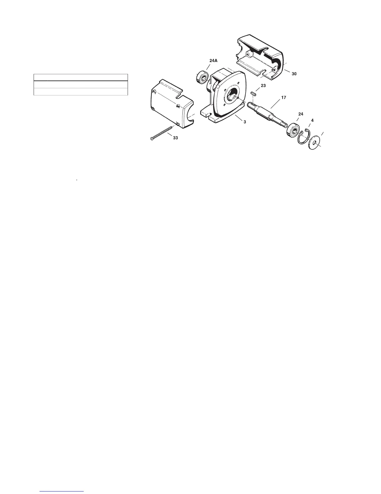
Figure 4-24 P3 Bearing Pedestal
Figure 4-24 P3 Bearing Pedestal
2. Place the shaft with either
bearing resting on top of the
jaws and gently tap on the end
of the shaft until the bearing is
removed. Refer to Figure 4-23.
3. Repeat step 2 to remove the
other bearing. Good support
used on the inner races will
Disassemble pump components
PUMP ENDS, 4E Disassembly
Multistage on C30 Motors / P30
The following tools and equipment
are needed for disassembly of the
1. Plastic or wooden mallet
3. Thin blade screwdriver
4. Adjustable spanner wrench
6. 7/16” Wrench or socket
When installing or removing bearings
from the shaft, the use of an arbor
press is strongly recommended.
To disassemble the pedestal:
Refer to Figure 4-28 for reference to
the numbered parts in the procedures
Mounting Brackets (#31) by
unscrewing Shoulder Screws
(#33C) with a 3/8” hex wrench.
2. Remove the four (4) Hex
Capscrews (#33B) that hold the
Bearing Frame Housing (#3)
to the End Bell (#101), using a
3. Position assembly horizontally
on workbench. Holding bearing
frame housing fi rmly, tap on the
coupling end of shaft with rubber
mallet until the assembly comes
4. Remove guide rod nuts and
guide rods from end bell.
5. Remove Outboard Bearing
(#24A) using a gear puller.
6. With a spanner wrench, unscrew
the Outboard Bearing Adjusting
Nut (#110A) from the end bell.
7. Support end bell, with motor
mounting face up, and press out
shaft / bearing assembly with
arbor press. Remove Inboard
Bearing Adjusting Nut (#110).
8. Disengage bearing lockwasher
tang from slot in Bearing
Locknut (#38), using a thin
blade screwdriver. Locknut and
Bearing Lockwasher (#39) may
now be removed from shaft.
Grip shaft in the area between
the two bearing surfaces only.
9. Place shaft / bearing assembly
in arbor press and remove the
4D Inspection of Components
Thoroughly clean all parts. All
components should be examined for
wear and corrosion. Replace any
parts showing visible wear.
Check to be certain that a press fi t
still exists between the shaft and the
bearings. New bearings, or at least
cleaned and regreased bearings, are
Check the shaft for galling, pitting,
and corrosion. Surface corrosion on
the pump portion of the shaft must
be removed so the seals will slide
freely during assembly. The shaft
diameter should be no smaller than
.002” below the nominal fractional
seal sizes. Remove any nicks or
burrs which may have occurred
during disassembly. Reclean parts
All parts should be visually inspected
and cleaned or replaced as outlined
in 4D above. It is recommended that
the bearings be replaced any time
the bearing pedestal is disassembled
The following tools and equipment
are needed for reassembly of P3
2. Rubber or plastic mallet
3. Internal snap ring pliers
4. 3/4” X 6” piece of water pipe
To reassemble the bearing frame:
Refer to Figure 4-24 for reference
to the numbered parts in the
1. Using an arbor press, install
the bearings on the shaft prior
to installing the shaft into the
pedestal. A steel “donut” with
the proper inside diameter and
outside diameter, refer to Chart
1, should be used between
the arbor face plate and the
lower bearing to insure proper
installation, and to prevent
bearing damage. The bearings
must seat against the shoulder
for proper alignment. Refer to
 Loading...