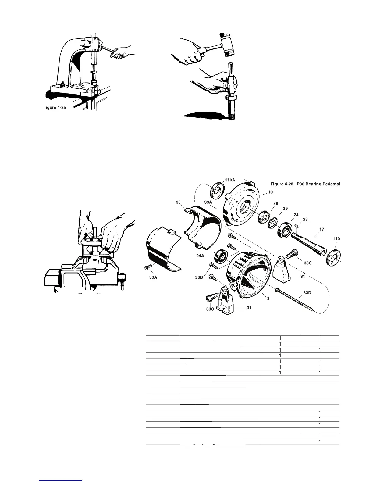
1. Stand a piece of 3/4” pipe,
with the threads cut off, on a
workbench or similar fl at surface,
with the bearing placed on the
2. Insert the shaft into the pipe so
the bearing is between the pipe
*Also refer to Alternate bearing
2. Place the pedestal, pump
mounting surface up, in a vise
or suitable fi xture and insert the
bearing assembly. It should
be possible to install the shaft
pressure. Refer to Figure 4-26.
If more force is required, the
butt end of a hammer handle or
plastic mallet may be helpful.
The shaft assembly should never
Figure 4-28 P30 Bearing Pedestal
and the shoulder of the shaft.
3. Using extreme caution, gently
tap on the end of the shaft until
the bearing rests against the
shoulder. Never attempt to install
the bearings by striking the outer
4. Repeat steps 1-3 for the
All parts should be visually inspected
and cleaned or replaced as outlined
in 4D above. It is recommended that
the bearings be replaced any time
the bearing pedestal is disassembled
Snap Ring / Bearing Retaining
Snap Ring / Bearing Retaining
Bearing Frame Mounting Bracket
Bearing Frame Mounting Bracket
Bearing Adjusting Nut - Inboard
Bearing Adjusting Nut - Inboard
Bearing Adjusting Nut - Outboard
Bearing Adjusting Nut - Outboard
3. Install the Snap Ring (#4) in the
pump end of the pedestal. Be
sure the snap ring is seated
properly in the groove. The
beveled edge of the ring should
face away from the bearing.
4. Install the Flinger (#21) over the
snap ring. The bearing pedestal
is now ready for pump and motor
*Alternate bearing installation
If an arbor press is not available,
the bearings may be installed on the
shaft using the following procedure:
This procedure is not recommended
and should only be used in an


 To Next Page
 Loading...