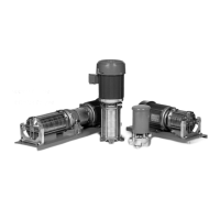
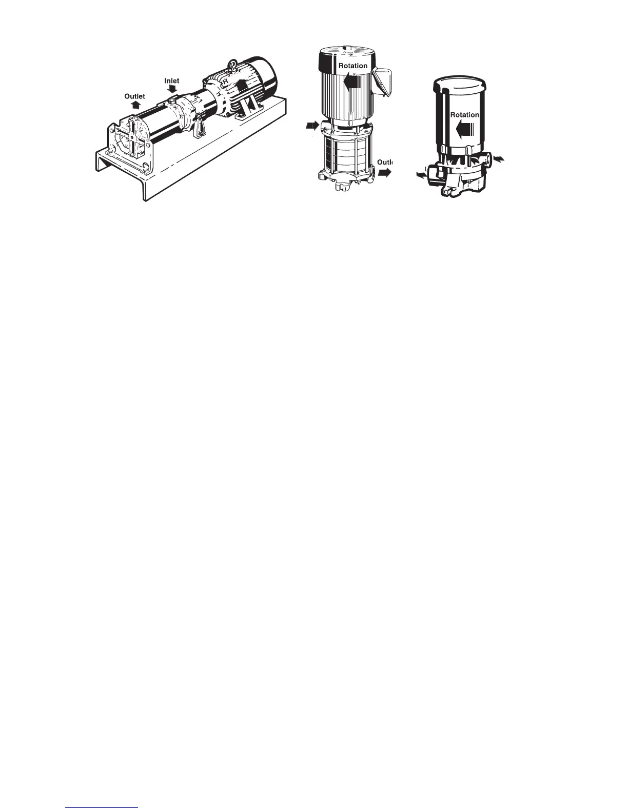
The pump inlet is located on the end
nearest the motor, except on Model
M51 - in which case it is farthest
form the motor. The discharge or
“outlet” can be on the top, side, or
bottom depending on the model and
construction of the pump. Normal
discharge position is located on
in horizontal confi gurations,
or in line with vertically mounted
All regenerative turbine pumps have
close running clearances in order
to maintain effi ciency. Take extra
precautions to insure that no foreign
material larger than 25 microns
or .001 inches is allowed to pass
through the pump. Even particles
of this size can damage the pump
if allowed to circulate continuously.
Regenerative turbine pumps are not
Large particles, weld spatter, and
other material found in new piping
systems will bend the impeller
vanes and can sometimes lock up
the pump. If a new pump does not
operate properly, the fi rst thing to
check for is damage from foreign
It is important to be aware of and
follow the appropriate local and
national electrical codes. Do
not make wiring alterations that
can affect motor rotation without
reconfi rming correct rotation.
making electrical connections to motors
provided with threaded stud electrical
terminals, the recommended torque
should be 13-16 inch-lbs. Applying
torque in excess of this range may cause
No adjustments are necessary or
advisable on new pumps other
than those required for installation.
Because of the close fi ts in
regenerative turbine pumps, it is
not uncommon for the pump to be
diffi cult to turn over by hand after the
internal parts have been allowed to
dry out. New pumps from the factory
are tested using rust inhibitors to
help preclude this possibility. On site
system fl ushing may remove these
inhibitors and subject the pump to the
risk of lock up, if it is allowed to dry
out. In this case, do the following:
1. Fill the pump with fl uid, then wait
2 hours prior to proceeding.
2. C3 Motors/P3 Bearing Frames
a. Using a 5/32” Allen wrench
using the Allen wrench as
verify there is not binding.
b. Remove the Allen wrench.
c. Jog the pump momentarily
binding or abnormal noise.
d. This should “break” the
3. C30 Motors/P30 Bearing Frames
a. Rotate the shaft to verify
from the outlet cover and
insert a 3/8” Allen wrench
into the socket end of the
shaft, using the wrench as a
handle. If draining fl uid from
the pump is not practical,
use the coupling on fl ex-
coupled units to turn the
shaft. Otherwise, a vise grip
or other plier-type gripping
device may be used directly
b. Remove the Allen wrench or
c. Replace the drain plug and
refi ll with fl uid, if the pump
d. Jog the pump momentarily
binding or abnormal noise.
e. This should “break” the
impeller(s) loose without
This procedure will fl ush residue from
the close fi tting impeller surfaces. If
not immediately successful, refer to
Section 1, 1C Placing Stored Pumps
Because of the large areas of close
fi tting surfaces inside these pumps,
it takes only microscopic residue to
produce resistance to rotation. Once
loosened, this material is quickly
dispersed and the impellers will
fi nd their hydraulic center. If these
procedures are followed carefully,
no damage will result from “breaking
When the pump is used to transfer
hot fl uids, consideration should be
given to cooling the seals and/or
selecting materials that will give
satisfactory seal life. The actual
temperature at the seal faces, the
most critical area, will always exceed
the surrounding fl uid temperature.
 Loading...