4.
Disassembly Vertical Single Stage
Disassembly Multistage on C3
Motors / P3 Bearing Frames
Disassembly Multistage on C30
Motors / P30 Bearing Frames
Reassembly Vertical Single Stage
Reassembly Multistage on C3
Motors / P3 Bearing Frames
Reassembly Multistage on C30
Motors / P30 Bearing Frames
Testing and Final Adjustments
Before attempting any service on
the pump or motor, disconnect the
electrical power to the motor. If the
pump and motor are to be removed as
a unit, note the wiring confi guration,
using colored or numbered tape.
1. Disconnect the inlet and outlet
piping before unbolting the pump
2. Unbolt the motor from the base
and remove the unit. All work on
the unit should be performed on
an elevated workbench whenever
The disassembly and reassembly
procedures are broken into eight
sections covering the following units:
— Disassembly Vertical Single
— Disassembly Multistage on C3
Motors / P3 Bearing Frames
— Disassembly Multistage on C30
Motors / P30 Bearing Frames
— Reassembly Vertical Single Stage
— Reassembly Multistage on C3
Motors / P3 Bearing Frames
— Reassembly Multistage on C30
Motors / P30 Bearing Frames
Exploded views of each unit, Figures
4-4, 4-11, and 4-12, are provided
for referencing the numbers in the
following procedures, i.e. (#1), motor
4B Disassembly Vertical Single
The following tools and equipment are
needed for disassembly of C3 units.
1. Soft plastic or wooden mallet.
2. 9/16” wrench or socket.
5. 1” wood dowel (Approx. 6” long).
6. Thin blade screwdriver.
7. Two large blade screwdrivers.
Refer to Figure 4-4 for reference to
the numbered parts in the procedures
1. Remove all liquid from the pump.
Air blown through the pump will
remove the fl uid quickly.
2. Remove the two (2) Nuts (#20)
and the two (2) 3/8” X 4” Bolts
(#19) from the Cover (#2). On
stainless steel models, remove the
3. Remove the cover (#2). In some
cases light tapping with a plastic
or wooden mallet on the outside
diameter of the cover may be
required to loosen it from the
motor bracket. Care should be
taken if a screwdriver is needed to
pry between the cover and motor
bracket. Damage to the “O” Ring
(#7) and/or impeller can result.
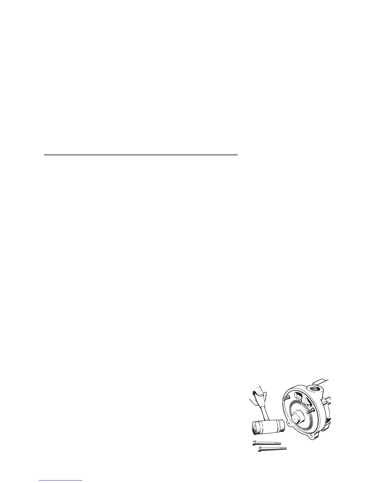
4. Remove the Impeller (#11). Refer
to Figure 4-1. The impeller is
a slip fi t and, under normal
conditions, can be removed by
gently tapping on the end of the
shaft sleeve with a mallet. Leave
the Impeller Key (#23) in place.
Striking the sleeve too hard could
damage the seat or rotating
5. Using the 5/32” hex wrench,
loosen the Set Screws (#15) in
the Locking Collar (#14), located
on the shaft sleeve between the
motor bracket and the motor face.
Pumps should not be operated
unless they are completely fi lled
with liquid. Damage to parts of the
pump that depend on liquid for their
lubrication can occur. Impellers can
seize quickly when a pump is run dry.
Without lubrication, seal faces can be
damaged from heat buildup.
Before starting a pump for the fi rst
time, be sure that all the preceding
operations have been carried out.
Proper rotation, priming, and a free
turning pump are most important.
1. Start the pump with the minimum
possible line restriction.
2. Open discharge valves before
3. Start the pump and let the
4. Listen for foreign material being
carried through the pump.
5. Slowly close necessary valves
or otherwise place the pump into
6. Listen for indications of undue
load or other sounds indicating
7. Use a clip-on ammeter to
check for a steady load after
approximately fi fteen minutes of
It is best to stop the pump with the
least discharge head possible both
for minimizing strain on components,
and to be in low power mode in
anticipation of restarting.
 Loading...