The collar should now be loose
on the sleeve. Note the condition
of the setscrews in the collar and
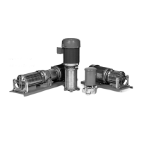
6. Remove the Shaft Sleeve
(#17). The sleeve is a keyed fi t
and is removed using two large
screwdrivers. Refer to Figure 4-2.
a. Insert the blades of the
spring holder on the rotating
element and the shoulder of
b. Holding the screwdrivers at
approximately 3 o’clock and
9 o’clock, push the handles
in toward the motor body,
using the motor bracket for
7. In some cases a rocking motion of
the screwdrivers will be necessary
to break the sleeve loose.
Normally the rotating element
will slide off with the sleeve. DO
NOT attempt to remove the sleeve
by rotating it. (Previous models
have used a threaded shaft and
different procedures are required
8. Remove the Seal Rotating
Element (#12) from the sleeve.
Refer to Figure 4-3. The element
normally adheres tightly to the
necessary to remove it. This is
common and if care is taken, the
element can be reassembled
that a new rotating element be
attempt to remove the seal using a
screwdriver or other sharp object.
Extensive damage to the shaft,
sleeve, or element could occur.
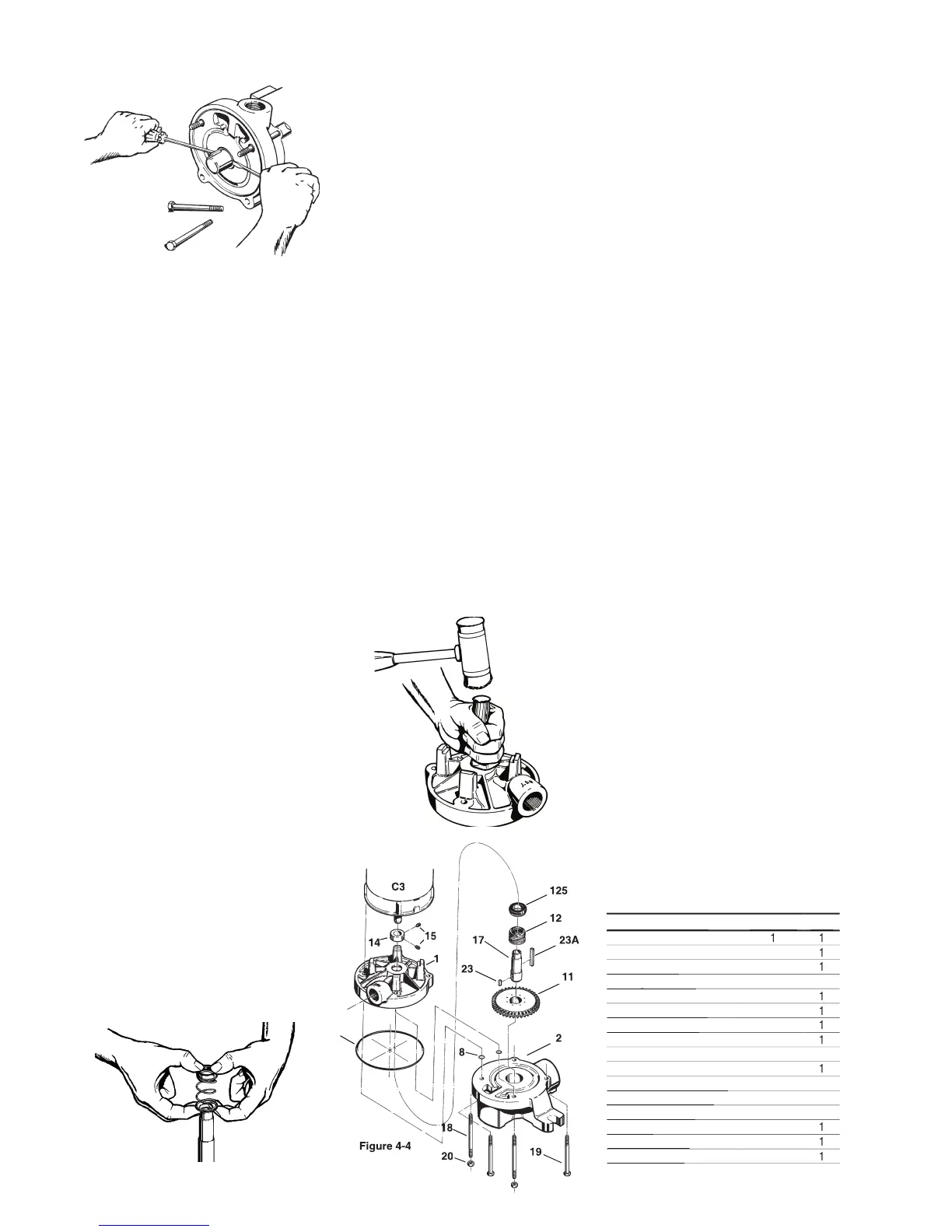
9. Before the motor bracket (#1) can
be removed, the four (4) “O”rings
(#8), located on the upper left and
right studs must be removed.
a. Gently tap on the back of the
motor bracket, alternately
between the left and the right
side, unit the motor bracket
moves approximately 1/4”.
b. Tap the motor bracket face
to move it back to its original
c. Remove the “O”rings by
sliding them off the studs.
d. Slide the motor bracket
straight off. Do not attempt
to remove the motor bracket
without fi rst removing the
Remove the Seal Stationary Seat
(#125). Refer to Figure 4-5.
a. Place the motor bracket face
b. Looking into the opening in
the center of the bracket, you
will see a portion of the seat.
c. Insert the 1” dowel and, very
gently, tap the seat until it
d. Care must be taken with
3. Repeat step 2 to remove the other
bearing. Good support used
on the inner races will prevent
Disassemble pump components as
shown in Section 4, M50 • L50 PUMP
ENDS, 4E Disassembly Multistage on
C30 Motors / P30 Bearing Frames.
The following tools and equipment are
needed for disassembly of the P30
1. Plastic or wooden mallet
3. Thin blade screwdriver
4. Adjustable spanner wrench
6. 7/16” Wrench or socket
When installing or removing bearings
from the shaft, the use of an arbor
press is strongly recommended.
Guide Rod (Qty. 4 on S.S.)
Guide Rod (Qty. 4 on S.S.)
 Loading...