Temposonics
®
R-Series V PROFINET IO RT & IRT
Operation Manual
I 11 I
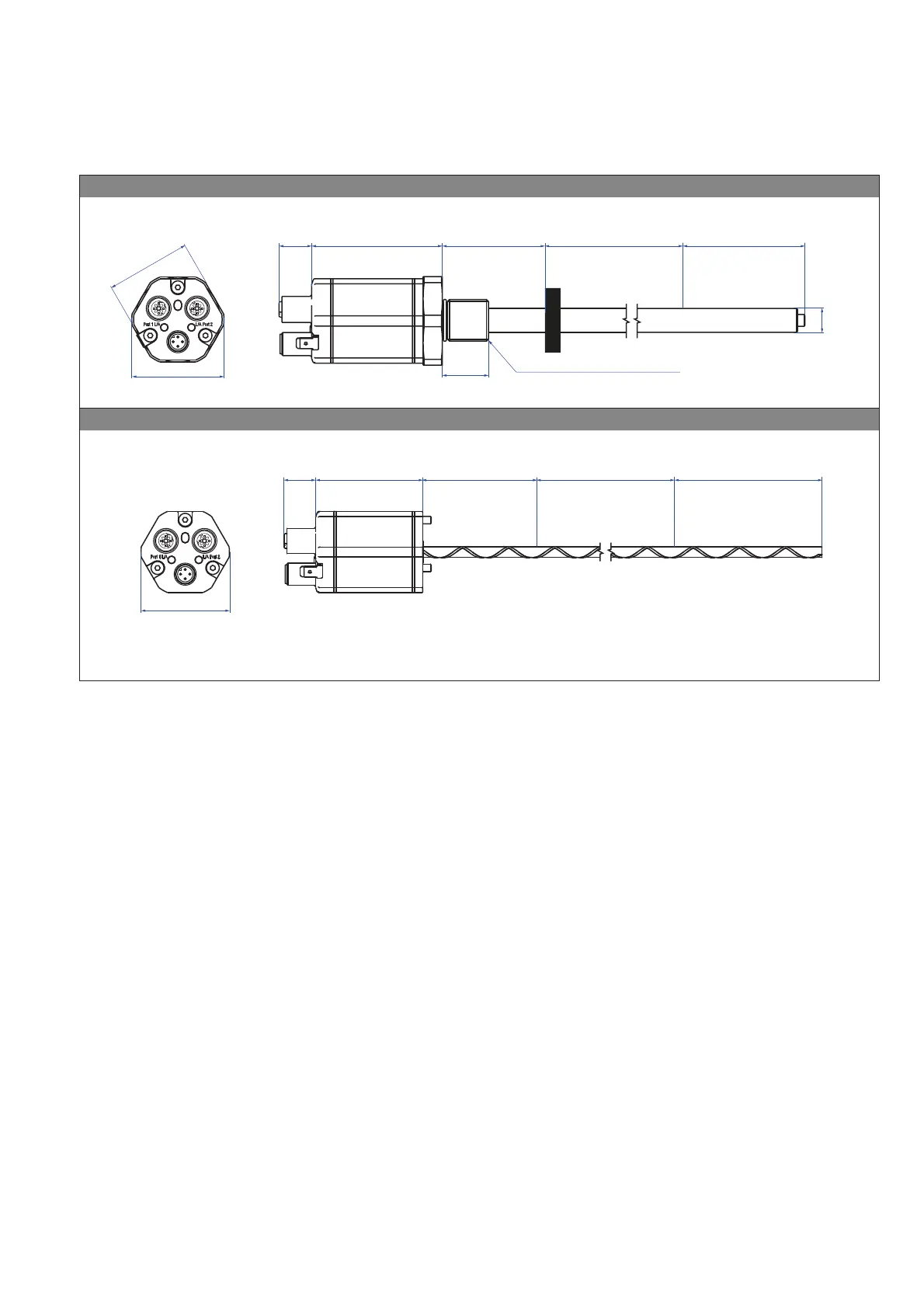
Fig. 7: Temposonics
®
RH5 with ring magnet, part 2
5+-$9ŋ5+ZLWKWKUHDGHGĠDQJH0ūJDQGPPURGH[DPSOH&RQQHFWLRQW\SH'FRQQHFWRURXWSXW
MSR
NSRN
1
45
2
1
45
2
A/F 46
17
(0.67)
Sensor electronics housing
68
(2.68)
Null one
51
(2.01)
Stroke length
25…5900
(1…232)
7KUHDGHGĠDQJH M22×1.5-6g
Magnet
Ø 12.7 ±0.13
(Ø 0.5 ±0.01)
Dead one
73.6
(2.9)
25
(0.98)
53
(2.09)
R5AV R5 base unit (only for replacement) eample Connection type D58 (connector output)
MSR
NSRN
1
45
2
1
45
2
48
(1.89)
17
(0.67)
Sensor electronics
housing
58
(2.28)
Null one
61
(2.4)
Stroke length
25…7620
(1…300)
Dead one
52/54/57**
(2.05/2.13/2.24)**
** Stroke length 25…1575 (1…62): 52 (2.05) dead zone
Stroke length 1576…5000 (62.05…196.9): 54 (2.13) dead zone
Stroke length 5001…7620 (196.9…300): 57 (2.24) dead zone
Controlling design dimensions are in millimeters and measurements in ( ) are in inches

 Loading...


