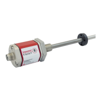
Do you have a question about the MTS Sensors Temposonics V SSI R Series and is the answer not in the manual?
| Brand | MTS Sensors |
|---|---|
| Model | Temposonics V SSI R Series |
| Category | Accessories |
| Language | English |
Explains the manual's purpose and intended audience for operating Temposonics sensors.
Defines symbols and warnings used in the documentation to highlight safety information.
Specifies the authorized applications and conditions for proper and safe product use.
Lists potential incorrect uses and their consequences to prevent damage or injury.
Provides safety guidelines for installation, setup, and ongoing operation of the sensors.
States that the sensors are not suitable for operation in explosion-hazardous areas.
Outlines the terms and limitations of the manufacturer's warranty for the sensors.
Details the procedure for returning sensors for diagnostics or repair.
Explains how to construct the order code for the RP5 sensor model.
Explains how to construct the order code for the RH5 sensor model.
Describes the information found on the sensor's nameplate.
Lists the certifications and approvals the sensor has received.
Details the components included in the sensor package for RP5 and RH5 models.
Provides an overview of the sensor's function, system design, and application fields.
Details the mounting and installation procedures for the RP5 sensor profile.
Details the mounting and installation procedures for the RH5 sensor rod.
Specifics on installing RH5 sensors using threaded flanges.
Guides for mounting rod-style sensors in hydraulic cylinders.
Explains methods for sealing flange connections in hydraulic systems.
Comprehensive guide for installing magnets with RP5 and RH5 sensors.
Guidelines for magnet installation when using magnetic materials.
Details the start/end positions for magnets to ensure full stroke usability.
Explains how differential measurements are performed using two magnets.
Guides for aligning magnets for sensors with internal linearization option.
Step-by-step instructions for replacing the sensor's base unit.
Details on connecting the sensor for proper electrical function and EMC.
Lists common accessories and optional parts for RP5 sensors.
Lists common accessories and optional parts for RH5 sensors.
Lists common accessories for SSI output configurations.
Introduces the Synchronous Serial Interface (SSI) and its data transfer capabilities.
Explains the sensor's LED indicators and their meaning for status monitoring.
Guides connecting the TempoLink smart assistant to the R-Series V sensor.
Details how to connect the TempoLink smart assistant to a power source.
Explains connecting the TempoLink assistant to devices for UI access.
Guides on accessing the TempoLink interface via a web browser.
Describes navigating and using the TempoLink smart assistant's graphical interface.
Setting the synchronization type for position measurement.
Setting the resolution of the position measurement.
Setting the internal linearization option.
Setting up filters for the output value.
Setting the time interval for SSI clock synchronization.
Setting the break between consecutive bar sequences.
Setting values transmitted during a failure.
Setting the time for outputting a power failure.
Setting how often errors are reported before displaying error values.
Refers to the commissioning chapter for error troubleshooting guidance.
States that the sensor is maintenance-free.
Outlines that repairs must be done by MTS or authorized facilities.
Indicates no spare parts are available for this sensor.
Mentions transport/storage conditions match operating conditions.
Provides detailed technical specifications for electrical connections.
Provides detailed technical specifications for electrical connections.
A form for customers to declare sensors are clean and safe for handling.
Provides detailed dimensional drawings for cylinder port configurations.