Temposonics
®
R-Series V SSI
Operation Manual
I 12 I
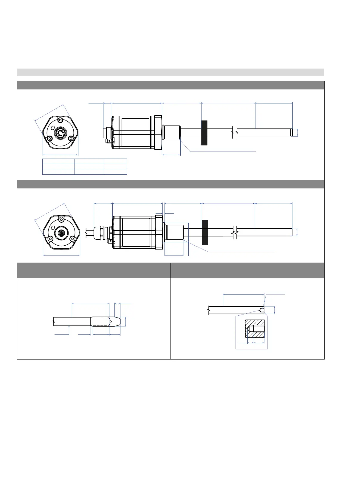
4.3 Installation Temposonics
®
RH5
Controlling design dimensions are in millimeters and measurements in ( ) are in inches
Fig. 6: Temposonics
®
RH5 with ring magnet, part 1
RH5-M/S-A/-V – RH5 with threaded ange M18×1.5-6g or ¾"-16 UNF-3A, example: Connection type D70 (connector output)
a
b
Sensor electronics housing
68
(2.68)
51
(2.01)
25
(0.98)
Threaded flange »M«: M18×1.5-6g
Threaded flange »S«: ¾"-16 UNF-3A
Magnet
63.5/66*
(2.5/2.6*)
25…7620
(1…300)
Ø 10 ±0.13
(Ø 0.39 ±0.01)
* Stroke length > 5000 mm (196.9 in.)
11.7
(0.46)
Threaded flange
»M«
»S«
a b
A/F 46 53 (2.09)
A/F 44.5 (1.75) 51.3 (2.02)
RH5-T-A/-V – RH5 with threaded ange ¾"-16 UNF-3A with raised-face, example: Connection type HXX / PXX / RXX / TXX (cable output)
A/F 44.5
(A/F 1.75)
51.3
Ø 25.4
(Ø 1)
Threaded flange »T«: ¾"-16 UNF-3A
25…7620
(1…300)
Sensor electronics housing
65.5
(2.58)
51
(2.01)
Magnet
* Stroke length > 5000 mm (196.9 in.)
Dead zone
63.5/66*
(2.5/2.6*)
Ø 10 ±0.13
2.5
(0.1)
25
25
(0.98)
Mechanical option »B«: Bushing on rod end for threaded ange
M18×1.5-6g or ¾"-16 UNF-3A
Mechanical option »M«: Thread M4 at rod end for threaded ange
M18×1.5-6g or ¾"-16 UNF-3A
63.5/66*
(2.5/2.6*)
22
(0.87)
15
(0.59)
3
(0.12)
8
(0.31)
Ø 12.8 ±0.1
Ø 10
(Ø 0.39)
* Stroke length > 5000 mm (196.9 in.)
70/72.5*
(2.76/2.85*)
3.5
(0.14)
6
(0.24)
Thread M4
Ø 10 ±0.13
(Ø 0.39 ±0.01)
* Stroke length > 5000 mm (196.9 in.)

 Loading...


