Temposonics
®
R-Series V SSI
Operation Manual
I 18 I
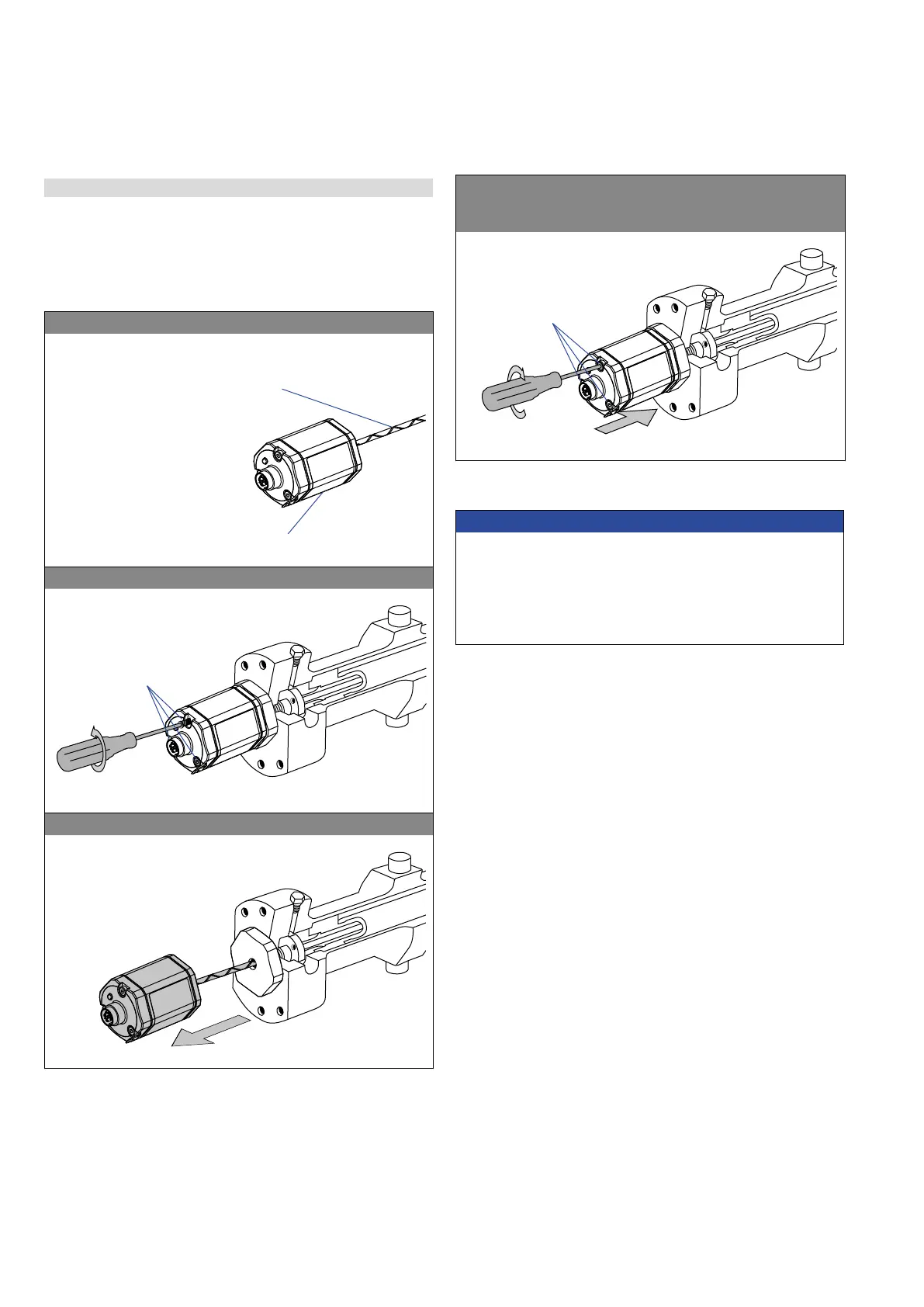
Fig. 23: Replacement of the base unit (e.g. RH5 sensor), part 1
Base unit
Sensor electronics housing
Tube with inner sensor element
1. Loosen the screws.
3 × socket head screw
M4 (A/F 2.5)
2. Pull out the base unit.
4.6 Replacement of base unit
The base unit of the sensor model RH5 (RH5-B) is replaceable as
shown in Fig. 23 and Fig. 24 for the sensor designs »M«, »S« and
»T«. The sensor can be replaced without interrupting the hydraulic cir-
cuit.
3. Insert the new base unit.
Install the ground lug on a screw.
Tighten the screws.
Fastening torque
1.4 Nm
Fig. 24: Replacement of the base unit (e.g. RH5 sensor), part 2
NOTICE
• If the R-Series V replaces a predecessor model of the R-Series,
the plastic tube in the sensor rod must be removed.
• When replacing the base unit, make sure that no humidity enters
the sensor tube. This may damage the sensor.
• Secure the base unit screws, e.g. using Loctite 243, before
re-installing.

 Loading...


