Temposonics
®
R-Series V SSI
Operation Manual
I 24 I
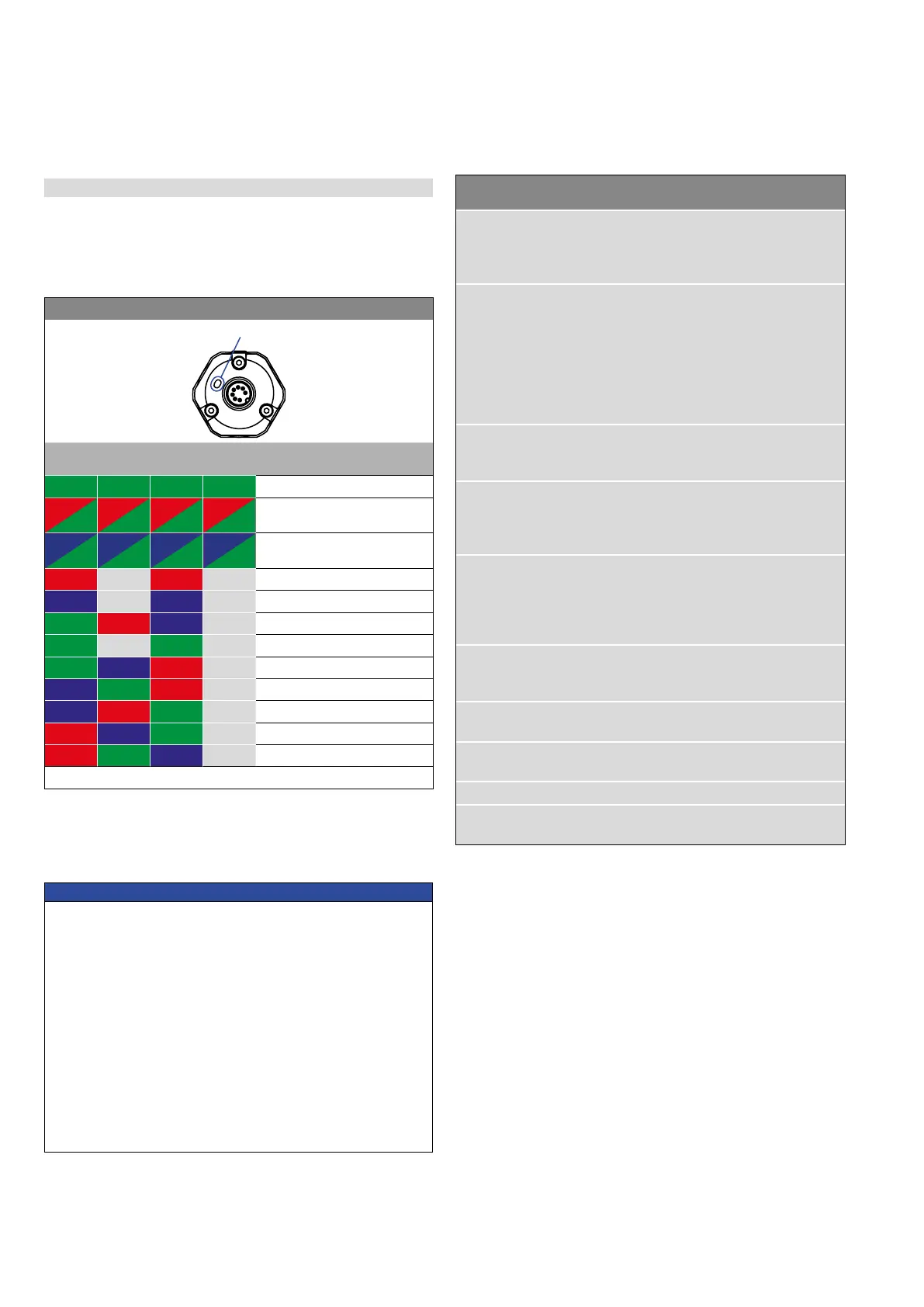
5.2 LED status
The LED on the sensor visualizes the current sensor status. In normal
function the LED is continuously green. In other cases the color of the
LED changes in the time slot of 0.5 seconds as shown in Fig. 33.
R-Series
SSI LED status
Time
slot 1
Time
slot 2
Time
slot 3
Time
slot 4
Information
GN GN GN GN Normal function
RD +
GN
RD +
GN
RD +
GN
RD +
GN
Magnet status error
BU +
GN
BU +
GN
BU +
GN
BU +
GN
Sync status error
RD Off RD Off Power supply error
BU Off BU Off Command Mode
GN RD BU Off Extra magnet
GN Off GN Off Cycle timeout
GN BU RD Off Con guration error
BU GN RD Off Storage error
BU RD GN Off Internal error
RD BU GN Off Signal error
RD GN BU Off Position error
1 × time slot = 0.5 seconds
Fig. 33: LED status
Fig. 34: Error conditions and troubleshooting
Error
condition
Description Troubleshooting
Magnet status
error
Sensor registers less
position magnets than
set
Ensure that the number of
position magnets on the
sensor matches the set
number.
Sync status
error
Sensor cannot syn-
chronize to the exter-
nal clock of the control
system
Adjust the parameter “Jit-
ter Window”.
Reduce the clock rate of
the polling cycle at the
control system.
Ensure that the control
system operates in syn-
chronous mode.
Power supply
error
Power supply of the
sensor is out of the al-
lowable range
Set the power supply for
the sensor to the allowable
range.
Extra magnet Sensor registers more
position magnets than
set
Ensure that the number of
position magnets on the
sensor matches the set
number.
Cycle timeout In synchronous mode,
the sensor does not re-
ceive the clock for the
polling cycle
Ensure that the clock of
the control system arrives
at the sensor. Ensure that
the control system oper-
ates in synchronous mode.
Conguration
error
Invalid conguration of
the sensor
Check the conguration of
the sensor.
Contact MTS Sensors.
Storage error Error in internal data
storage
Contact MTS Sensors.
Internal error Internal error of the
sensor
Contact MTS Sensors.
Signal error Internal signal error Contact MTS Sensors.
Position error Error in position mea-
surement
Contact MTS Sensors.
Fig. 34 describes error conditions that are output via the LEDs and
troubleshooting.
NOTICE
Observe during commissioning
1. Before initial switch-on, check carefully if the sensor has
been connected correctly.
2. Position the magnet in the measuring range of the sensor
during first commissioning and after replacement of the
magnet.
3. Ensure that the sensor control system cannot react in an
uncontrolled way when switching on.
4. Ensure that the sensor is ready and in operation mode after
switching on. The status LED lights permanently green.
5. Check the preset span start and end values of the measuring
range (see chapter 4.4) and correct them via the TempoLink
smart assistant, if necessary.

 Loading...


