Temposonics
®
R-Series V SSI
Operation Manual
I 5 I
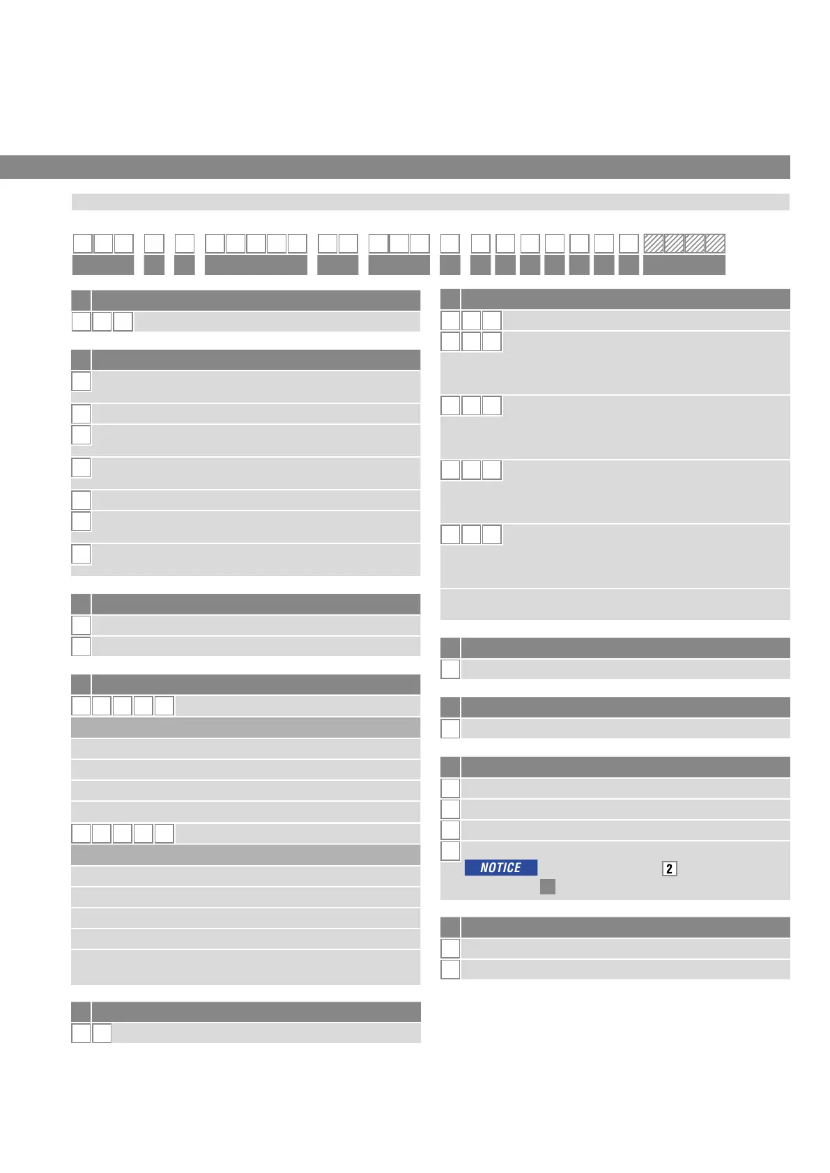
3.1 Order code Temposonics
®
RP5
3. Identication
e Number of magnets
X
X
01…02 position(s) (1…2 magnet(s))
f Connection type
D
7 0 M16 male connector (7 pin)
H
X X
XX m PUR cable (part no. 530 052)
H01…H30 (1…30 m/3…99 ft.)
See “Frequently ordered accessories” for cable
speci cations
P X X
XX m PUR cable (part no. 530 175)
P01…P30 (1…30 m/3…99 ft.)
See “Frequently ordered accessories” for cable
speci cations
R X X
XX m PVC cable (part no. 530 032)
R01…R30 (1…30 m/3…99 ft.)
See “Frequently ordered accessories” for cable
speci cations
T X X
XX m Tefl on
®
cable (part no. 530 112)
T01…T30 (1…30 m/3…99 ft.)
See “Frequently ordered accessories” for cable
speci cations
Encode in meters if using metric stroke length.
Encode in feet if using US customary stroke length.
g System
1
Standard
h Output
S
SSI
i Function
1
Position
2
Differential measurement (2 magnets and 1 output)
3
Velocity
4
Position and temperature in the sensor electronics housing;
In this case, only option
“24 bit” can be
selected under
l
“Data length”.
j Options
0
Standard
1
Internal linearization
a Sensor model
R P
5
Pro le
b Design
G
Magnet slider backlash free (part no. 253 421),
suitable for internal linearization
L
Block magnet L (part no. 403 448)
M
U-magnet OD33 (part no. 251 416-2),
suitable for internal linearization
N
Magnet slider longer ball-jointed arm (part no. 252 183),
suitable for internal linearization
O
No position magnet
S
Magnet slider joint at top (part no. 252
182),
suitable for internal linearization
V
Magnet slider joint at front (part no. 252
184),
suitable for internal linearization
c Mechanical options
A
Standard
V
Fluorelastomer seals for the sensor electronics housing
.
d Stroke length
X X X X M
0025…6350 mm
Standard stroke length (mm) Ordering steps
25… 500 mm 25 mm
500…2500 mm 50 mm
2500…5000 mm 100 mm
5000
…
6350 mm 250 mm
X X X X
U
001.0…250.0 in.
Standard stroke length (in.) Ordering steps
1… 20 in. 1.0 in.
20…100 in. 2.0 in.
100…200 in. 4.0 in.
200…250 in. 10.0 in.
Non-standard stroke lengths are available;
must be encoded in 5 mm/0.1 in. increments.
.
1 2 3 4 5 6 7 8 9 10 11 12 13 14 15 16 17 18 19 20 21 22 23 24 25 26 27
R P 5
1 S
a b c d e f g h i j k l m n o
optional

 Loading...


