Temposonics
®
R-Series V SSI
Operation Manual
I 7 I
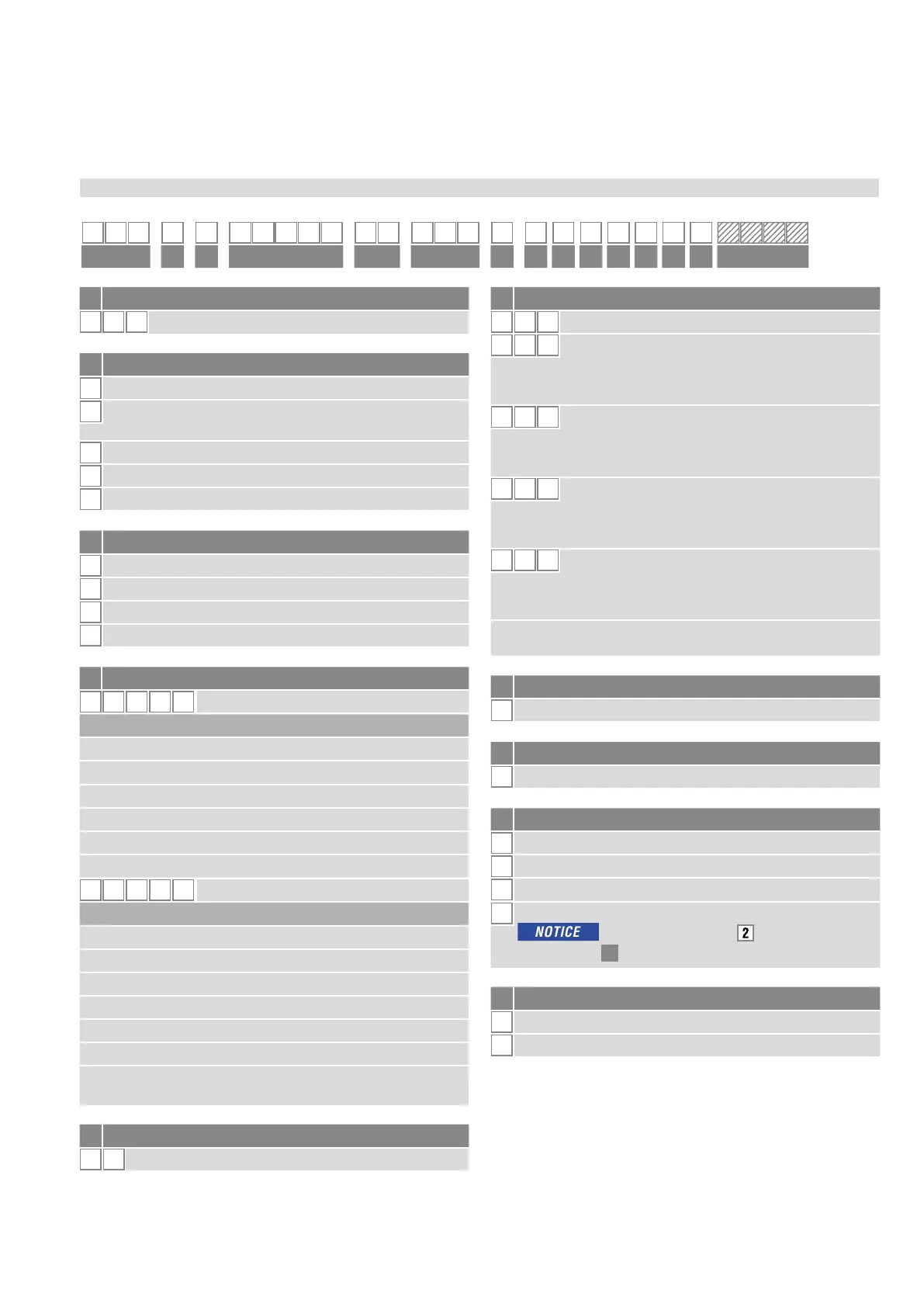
3.2 Order code Temposonics
®
RH5
e Number of magnets
X
X
01…02 position(s) (1…2 magnet(s))
f Connection type
D
7 0 M16 male connector (7 pin)
H
X X
XX m PUR cable (part no. 530 052)
H01…H30 (1…30 m/3…99 ft.)
See “Frequently ordered accessories” for cable
speci cations
P X X
XX m PUR cable (part no. 530 175)
P01…P30 (1…30 m/3…99 ft.)
See “Frequently ordered accessories” for cable
speci cations
R X X
XX m PVC cable (part no. 530 032)
R01…R30 (1…30 m/3…99 ft.)
See “Frequently ordered accessories” for cable
speci cations
T X X
XX m Tefl on
®
cable (part no. 530 112)
T01…T30 (1…30 m/3…99 ft.)
See “Frequently ordered accessories” for cable
speci cations
Encode in meters if using metric stroke length.
Encode in feet if using US customary stroke length.
g System
1
Standard
h Output
S
SSI
i Function
1
Position
2
Differential measurement (2 magnets and 1 output)
3
Velocity
4
Position and temperature in the sensor electronics housing;
In this case, only option
“24 bit” can be
selected under
l
“Data length”.
j Options
0
Standard
1
Internal linearization
1 2 3 4 5 6 7 8 9 10 11 12 13 14 15 16 17 18 19 20 21 22 23 24 25 26 27
R H 5
1 S
a b c d e f g h i j k l m n o
optional
a Sensor model
R H 5 Rod
b
Design
B
Base unit (only for replacement)
J
Threaded fl ange M22×1.5-6g (rod Ø 12.7 mm),
stroke length: 25…5900 mm (1…232 in.)
M
Threaded fl ange M18×1.5-6g (standard)
S
Threaded fl ange ¾"-16 UNF-3A (standard)
T
Threaded fl ange ¾"-16 UNF-3A (with raised-face)
c
Mechanical options
A Standard
B Bushing on rod end (only for design »M«, »S« & »T«)
M Thread M4 at rod end (only for design »M«, »S« & »T«)
V Fluorelastomer seals for the sensor electronics housing
d Stroke length
X X X X M
0025…7620 mm
Standard stroke length (mm) Ordering steps
25… 500 mm 5 mm
500… 750 mm 10 mm
750…1000 mm 25 mm
1000…2500 mm 50 mm
2500…5000 mm 100 mm
5000
…
7620 mm 250 mm
X X X X
U
001.0…300.0 in.
Standard stroke length (in.) Ordering steps
1… 20 in. 0.2 in.
20… 30 in. 0.4 in.
30… 40 in. 1.0 in.
40…100 in. 2.0 in.
100…200 in. 4.0 in.
200…300 in. 10.0 in.
Non-standard stroke lengths are available;
must be encoded in 5 mm/0.1 in. increments.
.

 Loading...


