Temposonics
®
R-Series V SSI
Operation Manual
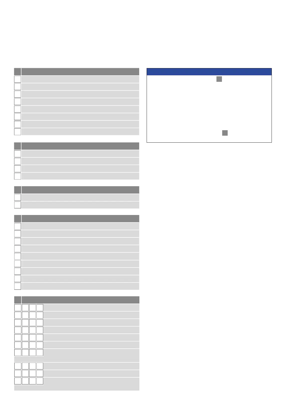
I 6 I
n Resolution
1
5 µm
2
10 µm
3
50 µm
4
100 µm
5
20 µm
6
2 µm
7
0.1 µm
8
1 µm
9
0.5 µm
m Format
B
Binary
G
Gray
o Additional options (optional)
S 0 0
2
FIR lter (2 measurements)
S 0 0
4
FIR lter (4 measurements)
S 0 0
8
FIR lter (8 measurements)
S 0 0 A
No lter, error counter (4 cycles)
S 0 0 C
No lter, error counter (8 cycles)
S 0 0 D
No lter, error counter (10 cycles)
S 0 0 G
FIR lter (8 measurements),
error counter (10 cycles)
S 0 0 J
IIR lter ( lter grade 4)
S 0 0 K
IIR lter ( lter grade 8)
S 0 0 N
IIR lter ( lter grade 4),
error counter (10 cycles)
k Mode
1
Measuring direction forward, asynchronous mode
2
Measuring direction forward, synchronous mode 1
3
Measuring direction forward, synchronous mode 2
4
Measuring direction forward, synchronous mode 3
5
Measuring direction reverse, asynchronous mode
6
Measuring direction reverse, synchronous mode 1
7
Measuring direction reverse, synchronous mode 2
8
Measuring direction reverse, synchronous mode 3
l Data length
1
25 bit
2
24 bit
3
26 bit
A
24 bit + alarm bit + parity bit
NOTICE
• For the RP5, the magnet selected in
b
“Design” is included in
the scope of delivery. Specify the number of magnets for your
application. For differential measurements order the second
magnet separately.
• The number of magnets is limited by the stroke length.
The minimum allowed distance between magnets (i.e. front face
of one to the front face of the next one) is 75 mm (3 in.).
• Use magnets of the same type for differential measurement,
e.g. 2 × U-magnet (part no. 251 416-2).
• If the option for internal linearization in
j
“Options” is chosen,
select a suitable magnet.

 Loading...


