Temposonics
®
R-Series V SSI
Operation Manual
I 29 I
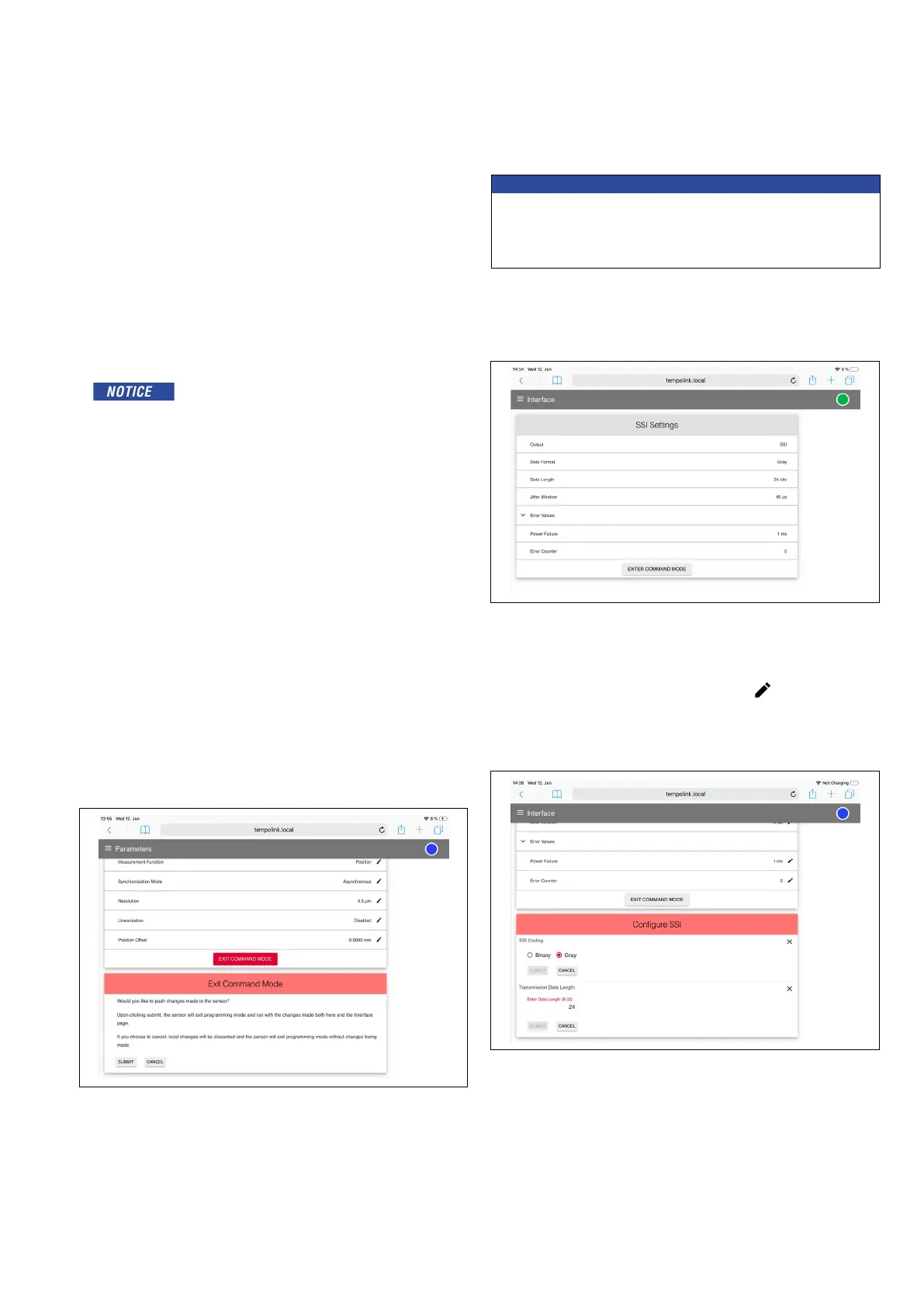
Fig. 51: Exit the command mode
NOTICE
Changes to the sensor parameters must also be set to the control
system.
Different parameter values on sensor and control system can lead to
unpredictable behavior of the control system.
Interface: Includes information about the interface settings of the
connected sensor (Fig. 52).
Fig. 52: Configuration of SSI settings
To change interface settings, start the command mode (page 28).
After entering the command mode a pencil icon
will appear to the
right of the setting values. By clicking the pencil icon a new menu for
configuring the settings will open. Change the parameter and confirm
it by clicking the “SUBMIT” button (Fig. 53).
Synchronization Mode: Setting the type of synchronization for the
position measurement.
• Asynchronous
• Synchronous mode 1
• Synchronous mode 2
• Synchronous mode 3
Resolution: Setting the resolution of the position measurement.
Linearization: Setting the internal linearization.
• Enabled
“Enabled” can only be activated if the sensor was
ordered with the option “internal linearization”.
• Disabled
Filter Conguration: Setting of the filter for the output value.
Filter Type: Setting the filter type.
• None: No filter (default value)
• FIR (Finite Impulse Response Filter)
• IIR (Infinite Impulse Response Filter)
Filter Window Size: Setting of position values for calculating the filter
of the output value.
By clicking the button “FACTORY RESET” the sensor is reset to
the factory setting. After the parameters have been configured or the
factory reset has been carried out, click the “EXIT COMMAND
MODE” button. A new menu for exiting the command mode will open
(Fig. 51). Click the “SAVE AND EXIT” button to exit the command
mode and to transfer the changed parameters to the sensor. The sen-
sor returns to the normal function and outputs the current position
value. The connection icon on the top right will turn to green. The sta-
tus LED of the sensor flashes green.
Fig. 53: Configuration of SSI settings
Data Format: Setting the SSI coding for the data transmission.
Data Length: Setting the bit width for the data transmission.

 Loading...


