Temposonics
®
R-Series V PROFINET IO RT & IRT
Operation Manual
I 18 I
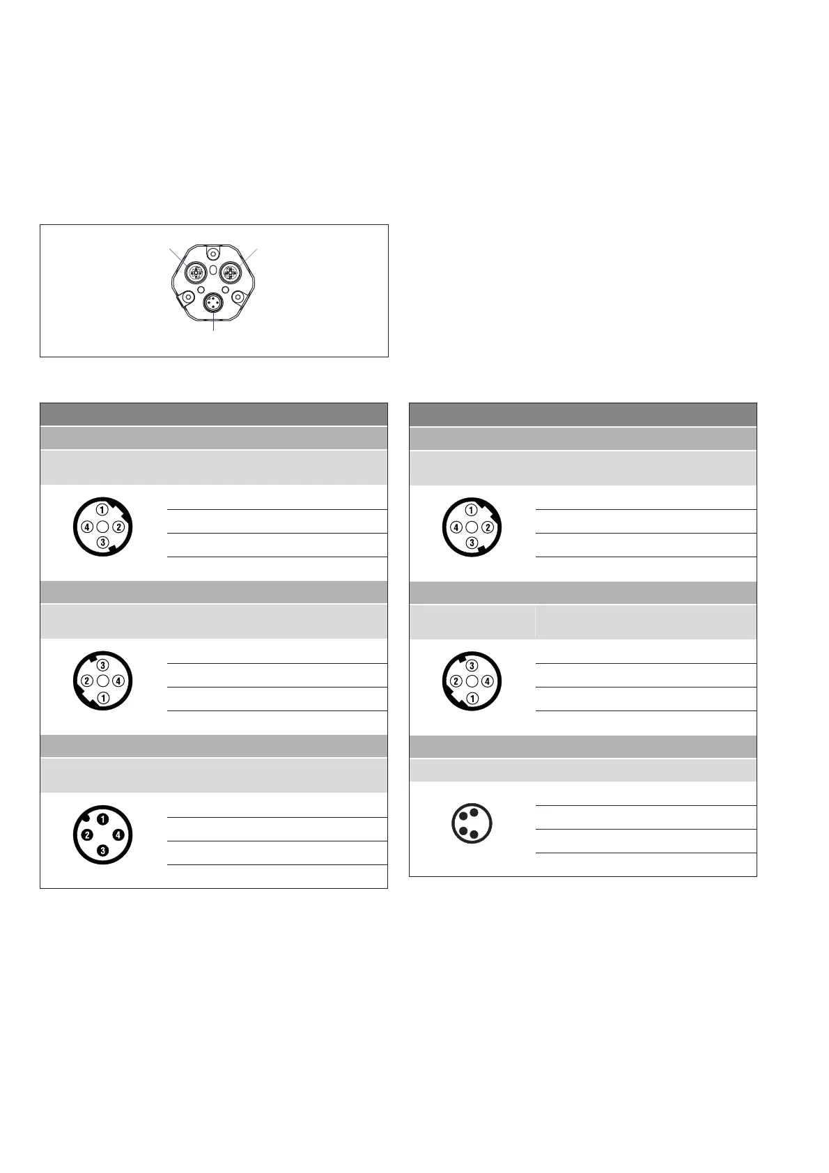
Connector wiring
Connect the sensor directly to the control system, indicator or other
evaluating systems as follows:
Fig. 26: Location of connections
Fig. 27: Connector wiring D58
ort Sina
a onntor
odd
in )XQFWLRQ
View on sensor
1 Tx (+)
2 Rx (+)
3 7[ũ
4 5[ũ
ort Sina
a onntor
odd
in )XQFWLRQ
View on sensor
1 Tx (+)
2 Rx (+)
3 7[ũ
4 5[ũ
or spp
a onntor
odd
in )XQFWLRQ
View on sensor
1 +12…30 VDC (±20 %)
2 Not connected
3 DC Ground (0 V)
4 Not connected
ort
SE
S
ort
1
45
2
1
45
2
Port 2Port 1
Power supply
ort Sina
a onntor
odd
in )XQFWLRQ
View on sensor
1 Tx (+)
2 Rx (+)
3 7[ũ
4 5[ũ
ort Sina
a onntor
odd
in )XQFWLRQ
View on sensor
1 Tx (+)
2 Rx (+)
3 7[ũ
4 5[ũ
or spp
a onntor in )XQFWLRQ
View on sensor
1 +12…30 VDC (±20 %)
2 Not connected
3 DC Ground (0 V)
4 Not connected
Fig. 28: Connector wiring D56

 Loading...


