Temposonics
®
R-Series V PROFINET IO RT & IRT
Operation Manual
I 26 I
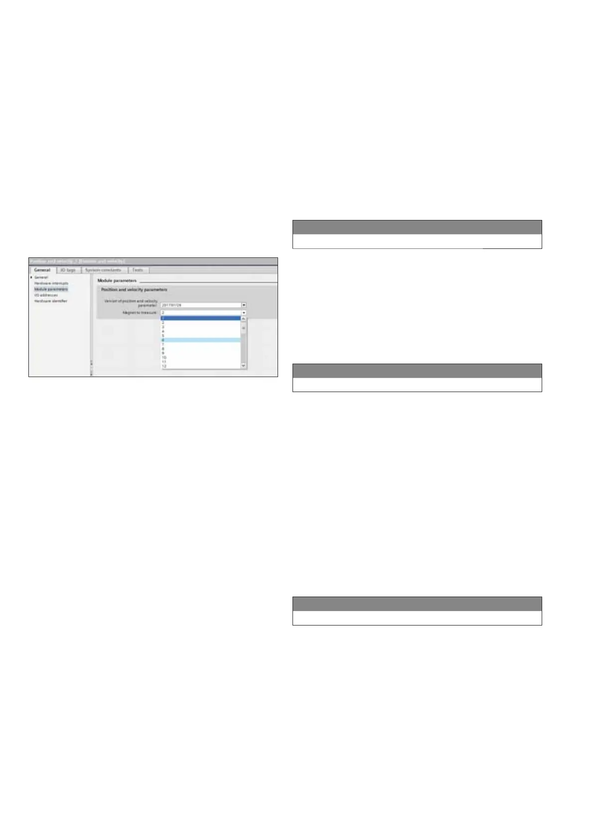
Drag the selected module into the "Device Overview" window. While
the "All positions" and "All velocities" modules contain up to 30
magnets, the "Position","Velocity" and "Position and velocity" modules
contain the values of only one magnet at a time. Therefore, a magnet
must be assigned to these modules. This assignment is carried out
in the "Module parameters" section of the module. Select a magnet
for the selected module under "Position parameters". By default, all
modules are assigned to magnet 1 (Fig. 377).
• Wrong Number of Magnets (Setting of the alarm behavior when
the actual number of position magnets differs from the specified
number of position magnets)
• More or less than configured
• More than configured
• Less than configured
• Magnet detection alarm off (default value)
The alarm is output via alarm ID 27 (Fig. 388).
• Power Supply Alarm (Setting of the alarm behaviour when the
power supply is out of the specified range).
• Supply voltage too high or too low
• Supply voltage too low
• Supply voltage too high
• Power supply alarm off (default value)
The alarm is output via alarm ID 17 (Fig. 399).
Alarm ID decimal (hexadecimal) Meaning
27 (1B) Wrong number of magnets
Alarm ID decimal (hexadecimal) Meaning
17 (11) Invalid operating voltage
• Velocity: This module contains the velocity of a magnet. Afterwards
you must assign a magnet to this module.
The parameters of the R-SeriesV PROFINET sensor are set in
the sub-section "Module parameters" of the sensor. The following
parameters can be adjusted in the "Sensor parameters" section
(Fig. 4141):
• Resolution (Setting of the resolution for position measurement)
Possible values: 0.5 µm; 1 µm; 2 µm; 5 µm; 10 µm; 50 µm or
100µm
• Filter Type (Setting of the filter for the output value)
• No filter (default value)
• FIR (Finite Impulse Response Filter)
• IIR (Infinite Impulse Response Filter)
• Filter Window Size (Setting of the number of position values for
calculating the filter of the output value)
Possible values: 2…16
• Velocity Window Size (Setting of the number of position values for
determining the velocity of the position magnet)
Possible values: 2…16
• Velocity Output Unit (Setting the unit of the velocity output)
Possible value: steps/1000 ms; steps/100 ms; steps/10 ms; mm/s
• Measuring Direction (Setting of the measuring direction for
position or velocity measurement)
• Forward (default value)
• Reverse
• Number of Magnets (Setting of the number of position magnets
that are used simultaneously on the sensor). If more magnets are
configured than specified in the order code, a parameterization
error is output. The alarm is output via alarm ID 16 (Fig. 4040).
• Extrapolation Mode (Setting of the sensor behaviour in case of
oversampling)
• On (The minimum cylce time of the sensor when the
Extrapolation Mode is on is 250 µs, independent of the number
of magnets)
• Off (default value)
• Internal Linearization (Setup of the internal linearization)
• Enabled (Internal linearization can only be activated if the table
of internal linearization is stored on the sensor.)
• Disabled (default value)
If the internal linearization is to be activated although the
corresponding table is not stored on the sensor, a parameterization
error is reported (Fig. 4040).
Alarm ID decimal (hexadecimal) Meaning
16 (10) Parameterization error
Fig. 37: Assignment of the magnets to the selected input modules
Fig. 38: Alarm messages: Wrong number of magnets – MTS Profile
Fig. 39: Alarm messages: Invalid operating voltage – MTS Profile
Fig. 40: Alarm messages: Parameterization error – MTS Profile

 Loading...


