EasyManua.ls Logo

MTU 16 V 4000 L62 - User Manual

MTU 16 V 4000 L62
187 pages
Print Icon
To Next Page IconTo Next Page
Loading...
Operating Instructions
Gas engine
12 V 4000 L62
16 V 4000 L62
MS150033/04E

Table of Contents

Questions and Answers

  • A
    Angela BlackAug 20, 2025
    What to do if my MTU Engine shows 'Lube Oil Min'?
    • D
      Denise BarnettAug 20, 2025
      If your MTU Engine displays a 'Lube Oil Min' message, it indicates that the minimum engine oil level has been detected. You should check the engine oil level and the replenishment system.
  • J
    Jason MitchellAug 21, 2025
    What to do if my MTU 16 V 4000 L62 Engine shows 'Lube Oil Max'?
    • J
      Jose Smith IIAug 22, 2025
      If the MTU Engine shows 'Lube Oil Max', this indicates that the maximum engine oil level has been detected. You should check the engine oil level and the replenishment system.
  • B
    Brenda ClarkAug 23, 2025
    What to do if the MTU 16 V 4000 L62 SS Coolant is too Low?
    • J
      juliandominguezAug 23, 2025
      If the MTU Engine indicates that the SS Coolant is too Low, it means there is a lack of coolant in the cooling system, and the feedback signal from the level sensor is missing. First, check the sensor and cabling, replacing them if necessary. Then, check the coolant level and try to pinpoint any leakage.
  • D
    Dale RodriguezAug 26, 2025
    What to do if my MTU 16 V 4000 L62 Engine loses Communication with ECU?
    • K
      Kathleen WilliamsAug 26, 2025
      If the MTU Engine displays 'Communication Lost ECU', it means there is no communication with the ECU CAN. Check the supply voltage and the connecting line.
  • A
    Ashley Church MDAug 27, 2025
    What to do if my MTU 16 V 4000 L62 loses Communication with EMU?
    • J
      Julie WilsonAug 27, 2025
      If the MTU Engine displays 'Communication Lost EMU', it indicates no communication with the EMU CAN. Check the supply voltage and the connecting line.
  • K
    kyle12Aug 29, 2025
    What to do if my MTU 16 V 4000 L62 shows 'Error Missing Ring Gear Signal'?
    • J
      John CurtisAug 30, 2025
      If the MTU Engine displays 'Error Missing Ring Gear Signal', it means the crankshaft signal for ignition speed 182 teeth is missing. You should check sensor B13.2, its clearance, and cabling, and replace it if necessary. Note that a restart of the ignition system is required to restart the engine.
  • M
    Meghan VelazquezAug 31, 2025
    What to do if my MTU 16 V 4000 L62 shows 'Error Missing Reset Signal'?
    • D
      David RowlandAug 31, 2025
      If the MTU Engine displays 'Error Missing Reset Signal', this indicates that the reset signal from the crankshaft is missing. Check sensor B75, its clearance and cabling, and replace if necessary. A restart of the ignition system is required to restart the engine.
  • H
    hpetersSep 3, 2025
    What to do if my MTU Engine shows 'Error Missing Camshaft Signal'?
    • J
      Jennifer SmithSep 3, 2025
      If the MTU Engine displays 'Error Missing Camshaft Signal', it means the camshaft signal for ignition is missing. Check sensor B1.2, its clearance, and cabling, replacing if necessary. Restart of the ignition system is required to restart the engine.
  • C
    colleendavidsonSep 4, 2025
    What to do if my MTU 16 V 4000 L62 loses Communication with Knock Module?
    • S
      Steven GarciaSep 5, 2025
      If the MTU Engine displays 'Comm. Lost Knock Module', it signifies no communication with the knocking module CAN. Check the supply voltage and the connecting line.
  • A
    ayalajennySep 6, 2025
    What to do if my MTU 16 V 4000 L62 Engine loses Communication with Ignition?
    • J
      Jeffrey MitchellSep 7, 2025
      If the MTU Engine displays 'Comm. Lost Ignition', it indicates no communication with the ignition CAN. Check the supply voltage and the connecting line.

Summary

Safety

General conditions

General safety instructions, correct use, modifications, spare parts, and component rework.

Personnel and organizational requirements

Requirements for personnel, organizational measures, and protective equipment.

Transport

Safety precautions for lifting, securing, and setting down the engine during transport.

Safety regulations for startup and operation

Precautions before operation and safety regulations during engine and electrical equipment operation.

Safety requirements for maintenance and repair work

Safety guidelines for personnel, gas-carrying components, tools, and general work practices.

Fluids and lubricants, fire prevention and environmental protection

Safety measures for fire prevention, noise, environmental protection, and handling of fluids.

Conventions for safety instructions in the text

Explanation of safety signal words (DANGER, WARNING, CAUTION, NOTICE) and their meanings.

Product Summary

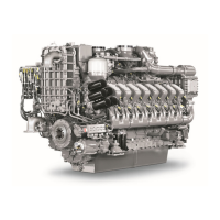
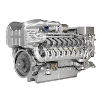
Engine - Overview

Overview of the engine with numbered components and their identification.

Engine side and cylinder designations

Designation of engine sides (A/B) and cylinder numbering from the driving end.

Engine - Main dimensions

Table of main engine dimensions (length, width, height, etc.) for 12V and 16V engines.

Ignition order

Ignition sequence for 12 V and 16 V engine configurations.

Technical Data

Detailed technical specifications including runtimes, reference conditions, and general data.

Monitoring, Control and Regulation Equipment

Gas engine phase 3 system - Overview

Overview of the gas engine phase 3 system components and governing/control functions.

Control cabinet MIS - Overview

Overview of the phase 3 gas engine control cabinet MIS, including its components and fuses.

Purpose of the units

Detailed functions of the Engine Governor ADEC (ECU 7) and its software structure.

Operation

Putting the engine into operation after extended out-of-service-periods (>3 months)

Preconditions and detailed steps for putting the engine into operation after long-term storage.

Putting the engine into operation after scheduled out-of-service-period

Preconditions and measures for putting the engine into operation after a scheduled shutdown.

Control, starting and stopping sequences

Description of the automatic sequences for engine start, stop, and emergency stop.

Starting the engine

Preconditions and safety notes for starting the engine.

Operational checks

Daily operational checks to ensure proper engine function and safety.

Stopping the engine

Preconditions and procedure for safely stopping the engine.

Emergency stop

Procedure for emergency stop, safety measures, and restart requirements.

After stopping the engine - Engine remains ready for operation

Status of the engine after stopping and before restart.

After stopping the engine - Putting the engine out of operation

Procedure for putting the engine out of service for extended periods.

Maintenance

50-hours check

One-time maintenance operations required after the first 50 operating hours.

Maintenance task reference table [QL1]

Reference table for maintenance tasks and their corresponding measures and page numbers.

Troubleshooting

Fault indication on SAM display

General abbreviations used in fault messages and fault indications on the SAM display.

SAM - Fault messages

List of fault messages originating from the SAM unit with causes and corrective actions.

Engine governor - Fault messages

List of fault messages from the engine governor with associated parameters and corrective actions.

Task Description

Engine - Barring manually

Procedure for manually barring the engine using special tools.

Checking machine room for smell of gas

Procedure for checking the machine room for gas leaks using detection equipment.

Oil separator - Filter replacement

Step-by-step instructions for replacing the oil separator filter.

Ignition system - Ignition timing check

Procedure for checking and adjusting the ignition timing using a stroboscope.

Spark plug connector - Replacement

Instructions for removing and installing a new spark plug connector.

Spark plug connector - Removal and installation

Detailed steps for removing and installing spark plug connectors.

Spark plug - Replacement

Instructions for removing and installing spark plugs.

Spark plug - Removal and installation

Detailed procedure for removing and installing spark plugs.

Valve gear - Lubrication

Procedure for lubricating the valve gear components.

Valve depth - Measurement

Steps for measuring valve depth using a depth gauge.

Valve clearance - Check and adjustment

Procedure for checking and adjusting valve clearances.

Valve gear - Lubrication

Procedure for lubricating the valve gear components.

Cylinder head cover - Removal and installation

Steps for removing and installing the cylinder head cover.

Gas supply - Checking gas lines for leaks

Procedure for checking gas supply lines for leaks using detection spray.

Air filter - Replacement

Instructions for replacing the air filter and optional fleece prefilter.

Air filter - Removal and installation

Detailed steps for removing and installing the air filter.

Engine oil level - Check

Procedure for checking engine oil level before and after engine start.

Engine oil - Change

Procedure for extracting old engine oil and filling with new oil.

Engine oil - Sampling and analysis

Procedure for extracting and analyzing engine oil samples.

Engine oil filter - Replacement

Instructions for replacing the engine oil filter.

Engine coolant - Level check

Procedure for checking the engine coolant level and system pressure.

Engine coolant - Change

Procedure for draining and filling the engine coolant.

Engine coolant - Draining

Detailed steps for draining engine coolant from various points.

Engine coolant - Filling

Procedure for filling the engine coolant system.

Vent line of engine coolant circuit - Replacement

Procedure for replacing the coolant vent line.

Mixture coolant level - Check

Procedure for checking the mixture coolant level.

Mixture coolant - Change

Instructions for draining and filling the mixture coolant system.

Mixture coolant - Draining

Procedure for draining charge-air coolant.

Mixture coolant - Filling

Procedure for filling the mixture coolant system.

Engine wiring - Check

Procedure for checking engine wiring, securing connections and cleaning components.

Sensors - Overview

Overview of sensors on the right engine side, driving end, and free end.

Appendix A

Abbreviations

List of abbreviations used in the manual with their meanings and explanations.

MTU Onsite Energy contact; service partner

Contact information for MTU Onsite Energy service and spare parts.

Appendix B

Special Tools

List of special tools required for maintenance tasks, with part numbers and usage.

Consumables

List of consumables required for maintenance tasks, with part numbers and usage.

Spare Parts

List of spare parts with part numbers and the tasks they are used in.

MTU 16 V 4000 L62 Specifications

General IconGeneral
Engine TypeDiesel
ConfigurationV16
Speed1800 rpm
Cooling SystemWater-Cooled
Model16 V 4000 L62

Related product manuals