EasyManua.ls Logo

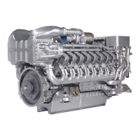
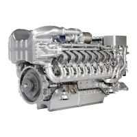
MTU 16V4000G34F User Manual

MTU 16V4000G34F
262 pages
To Next Page IconTo Next Page
Page #1 background imageLoading...
Page #1 background image
Operating Instructions
Diesel Engine
12V4000G34F
12V4000G94F
16V4000G34F
16V4000G94F
MS15060/01E

Table of Contents

Questions and Answers:

MTU 16V4000G34F Specifications

General IconGeneral
Engine Model16V4000G34F
Speed1800 rpm
Rated Speed1800 rpm
Number of Cylinders16
Bore170 mm
Stroke210 mm
Compression Ratio16.5:1
Cooling SystemWater-cooled
Emissions ComplianceEPA Tier 2
Engine TypeDiesel

Summary

Operating Instructions

1 Safety

1.1 Important provisions for all products

General safety provisions for all products, including risks and nameplates.

1.2 Important requirements for Power Generation application products

Requirements for power generation products, operational environment, residual hazards, and noise.

1.3 Gendrive engines – Intended use

Defines the intended use of Gendrive engines and modifications/conversions.

1.4 Personnel and organizational requirements

Requirements for personnel, training, and personal protective equipment.

1.5 Safety regulations for initial start-up and operation

Regulations for initial start-up, operation, malfunctions, and emergency stops.

1.6 Safety regulations for assembly, maintenance, and repair work

Safety regulations for work prior to, during, and after assembly, maintenance, and repair.

1.7 Fire and environmental protection, fluids and lubricants

Fire prevention, noise, environmental protection, disposal, and fluids/lubricants safety.

2 Transport

2.1 Transport

Special tools, material, spare parts for transport, and general transport instructions.

2.2 Lifting specifications

Safety warnings and specifications for lifting engines/generators, including center of gravity.

4 Technical Data

4.1 Product data 12V4000G34F, 12V4000G94F

Key for reference values, product data table, and reference conditions for 12V engines.

4.2 Product data 16V4000G34F / 16V4000G94F

Key for reference values, product data table, and reference conditions for 16V engines.

5 Functional Description

5.1 Engine models 12/16V4000G34F and 12/16V4000G94F – Overview

Provides an overview of the engine's driving end (KS) and free end (KGS).

5.7 Fuel system with Common Rail injection

Describes the fuel system, technical data, benefits, and operation of the Common Rail system.

5.8 Charge-air and exhaust system

Details the charge-air and exhaust system components, technical data, benefits, and operation.

5.12 Engine management and monitoring

Details engine management, monitoring systems, engine governor ECU 9, technical data, and functions.

6 Operation

6.1 Putting the engine into operation after extended out-of-service periods (>3 months)

Preconditions and steps for putting the engine into operation after extended periods of inactivity.

6.3 Starting the engine in manual mode (test run)

Preconditions, preparation, starting the engine, and connecting the generator for warm-up.

6.4 Re-starting the engine following an automatic safety shutdown

Notice regarding restarting after safety shutdown and procedure to follow.

6.5 Safety system – Override

Explains the override function for safety and shutdown alarms in emergency situations.

6.6 Operational monitoring

Details operational monitoring of control panels, engine oil, fuel prefilter, exhaust, intercooler, and air filter.

6.7 Emergency engine start (Override mode)

Procedure for emergency engine start using override mode, including preparation and connection to mains.

6.8 Stopping the engine in manual mode (test run)

Preconditions and steps for stopping the engine in manual mode, including generator preparation.

6.9 Emergency engine stop

Procedure for emergency engine stop using the pushbutton and actions after an emergency stop.

7 Maintenance

7.1 Maintenance task reference table [QL1]

Reference table for maintenance tasks and intervals, linking to the Maintenance Schedule.

8 Troubleshooting

8.2 Fault messages of the ADEC (ECU 9) engine governor for Series 4000 genset engines

Covers SS T-Coolant Intercooler, P-Lube Oil, and Coolant Level fault messages.

8.1 Troubleshooting

Troubleshooting for refdrive impossibilities and engine operation point faults.

9 Task Description

9.1.3 Engine – Test run

Outlines the steps for performing an engine test run and operational checks.

9.4.3 Valve clearance – Check and adjustment

Preconditions, special tools, preparatory steps, diagrams, and checking/adjusting valve clearance.

9.6 Injector

Special tools, material, spare parts, and overview of injector replacement.

9.6.2 Injector – Removal and installation

Preconditions, special tools, warnings, nameplate details, and steps for removal/installation.

9.8 Fuel Filter

Preconditions, special tools, warnings, and steps for replacing the fuel filter.

9.12 Lube Oil System, Lube Oil Circuit

Preconditions, special tools, warnings, and steps for draining and filling engine oil.

9.13 Oil Filtration / Cooling

Preconditions, special tools, warnings, and steps for replacing the engine oil filter.

9.20.4 Parameters for drift correction (CDC) – Resetting with DiaSys®

Note on emissions certification and procedure for resetting drift correction parameters with DiaSys®.

10 Appendix A

10.3 Tightening specifications for screws, nuts and bolts

Details tightening torques for SAE sealing cone with union nut JIC 37° and ORFS.

Related product manuals