S
spencerkathySep 13, 2025
What to do if coolant leaks at intercooler of MTU V 4000 M70 Engine?
- EErin HallSep 13, 2025
If you observe coolant leaks at the intercooler of your MTU Engine, especially with major coolant discharge, contact service.
What to do if coolant leaks at intercooler of MTU V 4000 M70 Engine?
If you observe coolant leaks at the intercooler of your MTU Engine, especially with major coolant discharge, contact service.
General safety information regarding engine operation and handling.
Guidelines for qualified personnel and organizational measures for safe operation.
Safety regulations and procedures for transporting the engine and its components.
Critical safety measures before, during, and after engine startup and operation.
Specific safety warning about explosion risks due to oil vapors when accessing the crankcase.
Comprehensive safety guidelines for all maintenance and repair activities on the engine.
Safety considerations for auxiliary materials, fire prevention, and environmental protection.
Explains the meaning of DANGER, WARNING, CAUTION, and NOTE signal words used in the manual.
Explains how engine sides and cylinders are designated for clarity and identification.
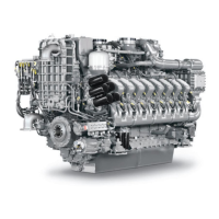
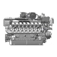
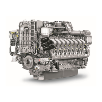
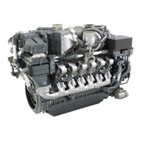
Provides a detailed description of the engine's main components and systems.
Illustrates the physical arrangement of engine components and systems for understanding.
Detailed technical specifications for the 8V 4000 M70 engine with specific cooling configuration.
Technical specifications for the 8V 4000 M70 engine with an engine-mounted heat exchanger.
Technical data for the 12V 4000 M70 engine with specific IMO and cooling configuration.
Technical specifications for the 12V 4000 M70 engine with specific IMO, cooling, and engine-mounted configuration.
Technical data for the 12V 4000 M70 engine with engine-mounted heat exchanger and EPA stage 2 compliance.
Technical specifications for the 12V 4000 M70 engine with separate heat exchanger and EPA stage 2 compliance.
Technical data for the 16V 4000 M70 engine with IMO and separate heat exchanger configuration.
Technical specifications for the 16V 4000 M70 engine with IMO and engine-mounted heat exchanger.
Technical data for the 16V 4000 M70 engine with IMO -20% and separate heat exchanger.
Technical specifications for the 16V 4000 M70 engine with IMO -20% and engine-mounted heat exchanger.
Technical data for the 16V 4000 M70 engine with engine-mounted heat exchanger and EPA stage 2 compliance.
Technical specifications for the 16V 4000 M70 engine with separate heat exchanger and EPA stage 2 compliance.
Technical data for the 12V 4000 M71 engine with IMO and separate heat exchanger configuration.
Technical specifications for the 12V 4000 M71 engine with IMO and engine-mounted heat exchanger.
Technical data for the 12V 4000 M71 engine with specific cooling and intake air temperature.
Technical data for the 16V 4000 M71 engine with IMO and separate heat exchanger configuration.
Technical specifications for the 16V 4000 M71 engine with IMO and engine-mounted heat exchanger.
Technical data for the 16V 4000 M71 engine with specific cooling and intake air temperature.
Lists the firing order for different engine configurations (8V, 12V, 16V, 20V).
Provides key physical dimensions (length, width, height) for various engine models.
Details the function and layout of controls on the Local Operating Panel (LOP) for engine operation.
Step-by-step procedure for re-commissioning the engine after prolonged inactivity.
Procedure for bringing the engine back into operation after a planned shutdown.
Specific tasks required for engines that have been out of service for more than three weeks.
Essential checks to perform on the engine and systems before initial startup.
Procedures for the initial startup and commissioning of the fuel treatment system.
Instructions for starting the engine using the Local Operating Panel (LOP).
Procedure for engine startup via the BlueLine automation system's control stand.
Steps to follow for activating and turning on the fuel treatment system.
Routine checks to perform on the engine during operation to ensure proper functioning.
Instructions for engaging the clutch using the Local Operating Panel (LOP) controls.
Instructions for disengaging the clutch using the Local Operating Panel (LOP) controls.
Optional procedure for flushing the waterjet system using LOP controls.
Steps for safely stopping the engine using the Local Operating Panel (LOP).
Procedure for stopping the engine via the BlueLine automation system's control stand.
Procedure for initiating an emergency engine stop using the Local Operating Panel (LOP).
Procedure for initiating an emergency engine stop via the BlueLine automation system.
Actions to take after the engine has been stopped, including draining and preservation.
Steps for properly shutting down and securing the fuel treatment system.
Guidelines and procedures for cleaning the engine plant, including safety precautions.
A table referencing maintenance tasks with associated task numbers and page locations.
General guidance for diagnosing and resolving common engine operational issues.
Explains fault messages displayed on the Local Operating Panel (LOP) for troubleshooting.
Procedure for manually rotating the engine crankshaft using a barring device.
Instructions on how to bar the engine using the automation system's starting functionality.
Method for inspecting cylinder liners using an endoscope for wear and damage.
Provides terminology and criteria for interpreting findings from cylinder liner endoscopic and visual inspections.
Procedure for checking the oil separator in the crankcase breather system for damage or excessive oil discharge.
Steps for replacing the oil separator, checking the diaphragm, and performing related maintenance.
Instructions for lubricating the valve gear components for proper engine operation.
Procedure for checking and adjusting valve clearances to ensure correct engine timing.
Steps for safely removing and reinstalling the cylinder head covers.
Procedure for checking the relief bore on the high-pressure (HP) injection pump for leaks.
Instructions for replacing the fuel injectors in the engine.
Detailed steps for removing and installing fuel injectors, including necessary tools and precautions.
Procedures for venting and filling the low-pressure (LP) fuel system to ensure proper fuel delivery.
Steps for replacing the fuel filter element to maintain fuel system efficiency.
Procedure for draining water and contaminants from the fuel prefilter.
Steps for flushing the fuel prefilter to remove blockages and contaminants.
How to check and adjust the differential pressure gauge on the fuel prefilter.
Procedure for replacing the filter element in the fuel prefilter.
Steps for inspecting the turbine housing of the exhaust turbocharger for cracks or damage.
Procedure for cleaning the compressor wheel of the exhaust turbocharger.
How to check the intercooler's condensate drain line for blockages and coolant leaks.
Instructions for removing the old air filter and installing a new one.
Detailed steps for removing and reinstalling the air filter assembly.
Procedure for checking the condition of the engine starter motor.
Instructions for operating the air starter manually for engine startup.
How to check the contamination indicator's signal ring position for air filter status.
Procedure for checking the air flap's movement to ensure it operates freely.
Steps for checking the engine oil level before and after operation.
Procedures for changing the engine oil, including draining and refilling.
Method for extracting and analyzing engine oil samples to assess condition.
Instructions for replacing the engine oil filter with the engine stopped or running.
Procedure for cleaning the centrifugal oil filter and replacing its filter sleeve.
Identifies the locations for venting air from the coolant circuit.
Steps for checking the coolant level at the filler neck, remote cooler, and via sensor.
Procedure for changing the engine coolant, including draining and refilling.
Steps for draining the engine coolant from various points in the system.
Procedure for filling the engine coolant system, with precautions for cold coolant.
Procedure for checking the relief bore on the engine coolant pump for discharge.
Method for extracting and analyzing coolant samples to check concentration and condition.
Procedure for checking the relief bore on the raw water pump for oil and water discharge.
Steps for checking the condition of the battery-charging generator drive coupling.
Procedure for checking and tightening securing screws on engine mounts for firm seating.
How to check the resilient elements of engine mounts for cracks or deformation.
Procedure for inspecting the condition of the drive system coupling.
Procedure for checking the relief bore on the bilge pump for oil and water discharge.
Steps for checking the water drain valve in the fuel supply system for proper function.
Procedure for checking the differential pressure gauge on the fuel treatment system.
Steps for checking the function of the 3-in-1 rod electrode water level probe.
Procedure for checking the pump's capacity and calculating wear limits.
Steps for replacing the coalescer filter element in the fuel treatment system.
Procedure for checking the engine wiring, connections, and cable integrity.
Instructions for cleaning the engine control unit and its connectors.
Procedures for cleaning the engine monitoring unit and its connectors.
Steps for checking the start interlock limit switch to ensure proper engine start prevention.
Procedure for verifying that all plug-in connections on the engine control unit are securely seated.
Procedure for verifying that all plug connections on the engine monitoring unit are securely seated.
Steps for removing and installing the engine control unit from the engine.
Guide for visually inspecting the Local Operating Panel (LOP) housing and internal assemblies for secure seating.
A list of abbreviations used in the manual with their meanings and explanations.
Lists spare parts with part numbers and their usage in various maintenance tasks.
Lists special tools required for maintenance and repair tasks, including part numbers.