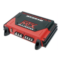
Control Panel
Gain Control - The gain control matches the input sensitivity of the amplier to the source unit being used. The
operating range varies from 100mv to 6V.
Adjusting the gain
1. Turn the gain control on the amplier all the way down (counter clockwise).
2. Turn up the volume control on the source unit to approximately 3⁄4 of maximum.
3. Adjust the gain control on the amplier until audible distortion occurs.
4. Adjust the gain control down until audible distortion disappears.
5. The amplier is now calibrated to the output of the source unit.
Low-Pass High-Pass X-Over Switch :
In “LPF” position, the active low pass (LP) x-over is turned on
In “HPF” position, the active high pass (HP) x-over is turned on
In “FULL” position, the x-over is turned o
High Pass X-Over Frequency Control :
Used to select the desired high-pass (HP) x-over frequency. The frequency is adjustable from 40Hz to 400Hz..
Low Pass X-Over Frequency Control :
Used to select the desired low-pass (LP) x-over frequency. The frequency is adjustable from 40Hz to 400Hz..
RCA Inputs - These RCA inputs are used with source units that have RCA or Line level outputs. (Source units need
a minimum level of 100mV output for proper operation of the amplier).
MTX recommends only high quality twisted pair cables (such as StreetWires) to decrease the possibility of radi-
ated noise entering the system.
RCA outputs - These RCA output jacks are for connecting multiple ampliers to 1 stereo RCA lead coming
from the source unit (daisy chaining).
PowerOn/Protection LED - The LED illuminates red when the amp is switched on. When the amps is in shortcir-
cuit or thermal protection, the LED is blinking. You need to switch o and on the amp to restart.
Speaker level inputs :
This input will allow the amplier to operate from source units with speaker-level outputs. Output speaker leads
from the source unit should be tied directly to the wire harness provided with the amplier.
Note : When speaker level inputs are used, a remote turn on wire must used to switch the amplier on and o.
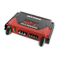
(+12V) Power Terminal - This is the main power input for the amplier and must be connected directly to the
positive terminal of the vehicles battery for proper operation. Use caution when installing (+12) power cable
in the vehicle. Avoid running this cable parallel with RCA cables, antennas, or other sensitive equipment due to
massive currents that can induce noise into the audio system. It is also very important to have a tight, secure con-
nection for maximum performance. MTX recommends using 10mm
2
power wire with the MTX RT251 amplier.
Remote Terminal – The amplier can be turned on by applying 12 volts to this terminal. Typically this voltage is
supplied by a wire from the source unit marked “remote” or “power antenna”.
Ground Terminal – A proper ground is required for your amplier to operate at peak performance. A short ground
cable the same diameter as the power cable should be used to attach the ground terminal directly to the chassis
of the vehicle. Always remove paint, dirt or debris to expose bare metal where the ground will be attached.
Speaker Terminals - Connect speakers to these terminals. Observe speaker polarity throughout the system. Im-
proper phase can result in loss of bass response and/or poor overall sound quality.
Fuses - When fuses blow, replace them with the same value. Never use a higher rated fuse !
EBC Port (External Bass Control) - The Remote Subwoofer Level Control (EBC) plugs directly into this port, while
the EBC itself can be placed anywhere in the vehicle for on demand bass adjustments. EBC is included.
Note : The EBC remote works only when the low pass xover is active (switch in LPF position).
 Loading...