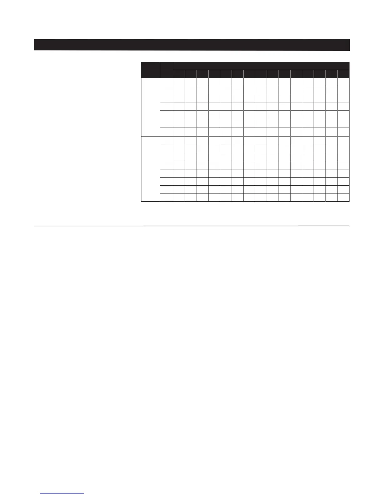
Thickness of Pipe Wall
This chart (right) gives the minimum
wall thickness of pipe that will
provide the recommended four full
threads of engagement with the
corporation stop inlet thread. For
pipe with thinner walls than specied
here, use Mueller Service Clamps
and Corporation Stops.
MUELLER
®
B-101
TM
and B-100
TM
Drilling and Tapping Machines
Maintenance Instructions
3
After Use
Thoroughly clean the entire machine
and all tools, and lubricate all
machined surfaces.
Remove all chips from inside the
body including the op valve recess.
A special body-cleaning chisel is
furnished for this purpose. If chips
are permitted to accumulate in
the machine, they could rust and
become caked and interfere with the
operation of the op valve.
NOTE: DO NOT bump machine on
hard surface to shake chips out
of body. Saddle gasket surface
is damaged by this type of
operation.
The machine and all tools and
equipment should be stored in the
machine chest. Carefully place tools
in their individual compartments to
prevent damage to the cutting edges.
Boring Bar Packing
Machine is equipped with O-ring
packings, which are nonadjustable.
When leakage occurs, replacement
is necessary.
NOTICE: The machine used to
illustrate this manual may differ
somewhat in appearance from
currently produced machines.
If one of these differences is of
signicance, it will be referred to
in the instructions.
Before Use
Clean and lubricate all wearing
and bearing surfaces and threads
EXCEPT the boring bar thrust collar
which requires no lubrication.
NOTE: If lubricated, service life
of boring bar thrust collar may be
shortened.
Boring bar is lubricated between
upper and lower O-ring seal in
feed sleeve and cap by a reservoir
containing light machine oil. Remove
oil plug in feed sleeve near lower
end and occasionally ll with light oil.
Inspect and clean all tools,
particularly the shank ends, and
remove any burrs or scale, which
would prevent proper alignment with
the boring bar.
Inspect and clean the socket in the
end of the boring bar and remove any
burrs or scale which would prevent
the tool from seating properly.
These packings are replaced in the
following manner:
1. Remove ratchet handle and feed
nut and yoke from boring bar.
2. Punch out boring bar thrust collar
retaining pin. Slide collar off bar.
3. Unscrew feed sleeve and cap
from cylinder and slide feed sleeve
and cap off bar.
4. Remove wiper ring and O-rings
from recess in top and bottom of
feed sleeve and cap.
5. Check wiper ring and O-ring
packing recesses to be sure they
are clean before placing new rings in
these grooves. New wiper ring and
O-ring packings should be lubricated
with machine oil or light grease
before they are placed in the feed
sleeve and cap.
6. Be sure the top end of boring
bar at squared end has no rough
edges or burrs that would damage
the new wiper ring and O-ring
packings as the feed sleeve and
cap are replaced on the boring bar.
Screw feed sleeve and cap back on
cylinder.
Tools and saddles are offered for
use with cast iron, ductile iron, steel
and asbestos-cement pipe in sizes
from 2” to 48”.
Maximum Working Pressure
90psi without power clevis
250psi with power clevis
1
/2” .33 .32 .31 .30 .30 .30 .30 .29 .29 .29 .29 .29 .29 .28 .28
5
/8” .36 .35 .32 .31 .31 .30 .30 .30 .29 .29 .29 .29 .29 .29 .28
3
/4” .37 .36 .35 .34 .33 .33 .32 .32 .32 .32 .31 .31 .31 .31 .31
1” .46 .44 .40 .39 .38 .37 .36 .36 .36 .35 .35 .35 .34 .34 .34
1
1
/4” .57 .52 .47 .44 .42 .41 .49 .39 .39 .39 .38 .37 .37 .37 .37
1
1
/2” .64 .58 .51 .47 .45 .43 .42 .41 .40 .40 .39 .38 .38 .37 .37
2” .86 .75 .61 .55 .51 .48 .46 .45 .44 .43 .42 .40 .40 .39 .38
1
/2” .330.322.311.305.301.299.297.296 .295.295.292 .291.290.289.289
3
/4” .356.343.325.316.310.306.304.301 .300.298.296 .294.293.292.291
1” .459.438.411.396.387.381.376.373 .370.368.365 .361.359.358.356
1
1
/4” .528.493.449.425.410 .400.393 .388 .383 .380 .375 .370 .366 .363.361
1
1
/2” .588.540.481.449 .430 .417 .407.400 .394.390.383 .376.372.368.366
2” .740.657.558.508.477.456.441.430 .421.414.403 .392.385.380.376
2
1
/2” — .968.812.736.689.658.636.620 .607.596.580 .565.554.546.541
3” — — .975.855.784.737.704.679 .659.644.620 .596.580.569.560
AWWA
Taper
Thread
AWWA
I.P.
Thread
Maintenance Instructions
 Loading...