MUELLER
®
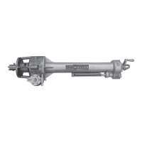
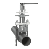
C1-36 Drilling Machines
Maintenance Instructions
2 3
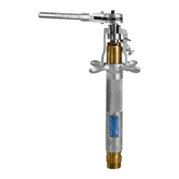
5. Remove gland from boring bar.
6. Place gland in a vise or clamp so
that packing will not “spring” out of
gland when the two retaining pins
(Part No. 47092) are removed.
7. Remove retaining pins.
8. Model 3 and prior: Remove
concave follower, four packing rings,
convex follower, and spring from the
gland.
9. Remove any burrs from the boring
bar drive lugs. Lubricate the boring
bar and inside of the new packing
rings with a light lm of oil or cutting
grease.
10. Remove cap screws from
alternate tapped holes in gland.
11. Replace boring bar wiper ring
(Part No. 501158) and gland seal
(Part No. 52162) if necessary. Place
gland on boring bar being careful not
to damage packing ring or the wiper
ring.
12. Slide gland into ange recess.
Insert and tighten cap screws
securely.
13. Replace hub retaining bolt and
nut.
Cutters
SHARPEN CUTTERS AND PILOT
DRILLS BY TOUCHING THEM UP
WITH AN OILSTONE BEFORE
EACH CUT. If the cutters are
very dull, return to Mueller Co. for
reconditioning.
OILING (Model 4, 5 & 6) for model
3 or earlier call Mueller Customer
Service.
Keep the drive box and rear gear
case of torque tube half full of a
good grade, extreme pressure semi-
uid gear oil with a Saybolt Universal
Viscosity of 80-85 seconds at 210°F.
Change oil periodically. Drain old oil
and replace with 4 pints in drive box
and 1.6 pints in rear gear case of
torque tube. Mueller Part No. 89347
gear oil is used and needs not
thinning in cold weather.
Packing
Boring Bar Packing is the self-
adjusting type. If packing leaks.
Replace it as follows:
1. Remove hub retaining bolt (Part
No. 545513) and nut (Part No.
61707) from boring bar.
2. Remove 4 cap screws (Part No.
53542) from the gland (Part No.
501151).
3. Insert cap screws into the
alternative tapped holes in gland
and screw them in all the way. This
should be done evenly, tightening
each cap screw a little at a time. This
will cause the gland to move forward
evenly out ot the gland recess until
the gland seal (Part No. 52162) is
exposed.
4. Rotate crank handle (Part No.
88150) counter-clockwise and
advance boring bar 6 or 8 inches.
This will cause the gland to move
forward into an exposed position.
CAUTION: Keeping cutters
sharp assures maximum
efciency in cutting operations.
When cutters are dull they not
only make cutting more difcult,
but place an additional strain on
the teeth which can cause tooth
breakage. When not in use, keep
cutters in the machine chest or
other wooden container. (NOTE:
Be careful not to drop cutter and
damage cutter teeth.) If necessary
to rest cutter on teeth, place upon
wood rather than brick, concrete,
or metal.
After Use
Clean dirt, etc., from machine and
equipment. Give cutters, drills,
and equipment a light coat of oil to
protect them from rust.
Storage
When not in use, the machine and
equipment furnished with each
machine should be stored in the
chest furnished with the machine.
NOTE: If the machine is stored
or transported in the vertical
position. It is recommended
that before use it be placed in a
horizontal position for a short
period of time (
1
/2 hour), to allow
grease to drain back into the rear
grease case.
Maintenance of Machines and Equipment
!
 Loading...