MUELLER
®
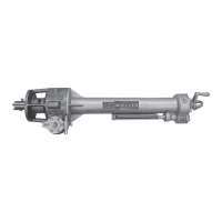
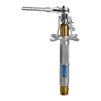
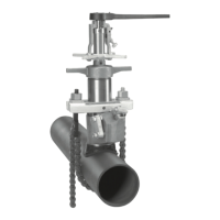
C1-36 Drilling Machines
Travel Charts
8 9
NOTE: All dimensions are in inches and are the travels required to complete the cuts plus
1
/4” (6mm) of over
travel unless otherwise noted.
*These dimensions are based on the shell cutter advancing to the center of the main.
1
1
/2”
2”
2
1
/2”
3”
3
1
/2”
4”
5
1
/2”
6”
7
1
/2”
8”
9
1
/2”
10”
10
13
/16”
12”
2
1
/2”
3”
3
1
/2”
4”
5
1
/2”
6”
7
1
/2”
8”
9
1
/2”
10”
10
13
/16”
12”
3
1
/2”
4”
5
1
/2”
6”
7
1
/2”
8”
9
1
/2”
10”
10
13
/16”
12”
1
3
/8
1
1
/2
1
3
/4
1
3
/4
1
1
/2
1
3
/4
2
2
5
/8
2
7
/8
3
2
1
/2
3
1
/2
3
5
/8
3
7
/8
1
3
/4
1
3
/4
1
1
/2
1
3
/4
2
2
5
/8
2
7
/8
3
2
3
/4
3
1
/4
3
1
/2
3
3
/4
1
1
/2
1
7
/8
1
3
/4
2
5
/8
2
7
/8
3
2
1
/2
3
1
/4
3
1
/4
3
1
/2
1
1
/2
1
5
/8
1
7
/8
1
7
/8
1
1
/2
1
7
/8
2
2
3
/4
3
1
/8
3
1
/4
2
1
/2
3
5
/8
3
3
/4
4
1
/8
2
2
1
1
/2
2
2
2
7
/8
3
1
/8
3
1
/4
2
3
/4
3
5
/8
3
3
/4
4
1
3
/4
2
1
3
/4
2
7
/8
3
1
/8
3
1
/8
2
3
/4
3
3
/8
3
1
/2
3
5
/8
1
1
/2
1
3
/4
1
7
/8
1
7
/8
1
1
/2
1
7
/8
2
2
7
/8
3
1
/8
3
1
/4
2
1
/2
3
3
/4
3
7
/8
4
1
/4
1
7
/8
2
1
1
/2
1
7
/8
2
2
7
/8
3
1
/8
3
1
/4
2
3
/4
3
5
/8
3
3
/4
4
1
3
/4
2
1
3
/4
2
7
/8
3
3
1
/8
2
3
/4
3
3
/8
3
1
/2
3
5
/8
1
3
/4
2
2
1
/8
2
1
/8
1
3
/4
2
1
/8
2
1
/2
3
3
3
/8
3
1
/2
3
3
7
/8
4
1
/8
4
3
/8
2
1
/8
2
1
/4
1
3
/4
2
1
/8
2
1
/2
3
3
1
/4
3
3
/8
3
3
3
/4
3
7
/8
4
1
/4
1
3
/4
2
1
/4
2
1
/2
3
1
/8
3
3
/8
3
3
/8
3
3
5
/8
3
3
/4
4
1
3
/4
1
3
/4
1
1
/2
1
3
/4
2
2
5
/8
2
3
/4
3
2
1
/2
3
1
/4
3
3
/8
3
3
/4
1
1
/2
1
3
/4
2
2
1
/2
2
3
/4
2
7
/8
2
3
/4
3
1
/8
3
1
/4
3
3
/8
1
3
/4
1
7
/8
1
1
/2
1
3
/4
2
2
3
/4
3
3
2
1
/2
3
3
/8
3
1
/2
3
7
/8
1
1
/2
1
7
/8
2
2
3
/4
2
7
/8
3
2
3
/4
3
1
/4
3
3
/8
3
1
/2
1
3
/8
1
1
/2
1
3
/4
1
3
/4
1
3
/4
1
3
/4
2
5
/8
2
5
/8
3
3
1
/8
2
3
/4
3
5
/8
3
7
/8
4
3
/8
1
3
/4
1
3
/4
1
1
/2
1
3
/4
2
2
5
/8
2
7
/8
3
2
3
/4
3
1
/2
3
5
/8
4
1
1
/2
1
3
/4
2
2
5
/8
2
7
/8
3
2
3
/4
3
3
/8
3
3
/8
3
7
/8
1
3
/4
1
7
/8
2
1
/8
2
1
/8
2
1
/8
2
1
/4
3
3
1
/8
3
3
/8
4
3
1
/4
4
1
/8
4
3
/8
4
7
/8
2
1
/8
2
1
/4
1
3
/4
2
1
/4
2
1
/2
3
1
/8
3
3
/8
3
1
/2
3
1
/4
4
1
/8
4
1
/8
4
5
/8
1
3
/4
2
3
/8
2
1
/2
3
1
/
3
1
/2
3
1
/2
3
1
/4
3
7
/8
4
4
3
/8
2
5
/8
4
2
3
/4
3
5
/8
4
4
7
/8
18”
20”
24”
CLASS 150
Outside
Diameter
of Cutter
ASA A 21.6.1953
ASA A 21.8.1953
AWWA C106-53
AWWA C108-53
CLASS 150
ASA A 2.1953
AWWA C102-53
CLASS 150
AWWA
1908 Standard
CLASS B
AWWA
1908 Standard
CLASS D
ASA A
21.7.1953
ASA A
21.9.1953
CLASS 10
AGA
Old
Standard
Schedule
40
Schedule
80
Nominal
Size
of Pipe
to be Cut
TRAVEL REQUIRED TO COMPLETE A CUT FOR LATERAL CONNECTION WITH POINT
OF PILOT DRILL (OR SOLID DRILL) CONTACTING MAIN
CAST IRON PIPE STEEL PIPE
ASBESTOS
CEMENT PIPE