M0588.docx | Rev 1.5 | Modified on 12/11/2018 | © Remote Control Technologies Pty Ltd
Table of Figures
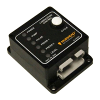
Figure 1 Programmable lubrication controller .................................................................................................. 7
Figure 2 Drawing 427i Single bank system external wiring diagram .............................................................. 11
Figure 3 Drawing 427h Dual bank system external wiring diagram ............................................................... 12
Figure 4 Drawing 427j Basic programming adaptor lead external wiring diagram ......................................... 13
Figure 5 Drawing 423a – In-line programming adaptor lead loom configuration ........................................... 14
Figure 6 Lube controller application ............................................................................................................... 15
Figure 7 Home screen – lube controller application ....................................................................................... 15
Figure 8 Layout of the main set-up screen ..................................................................................................... 16
Figure 9 Device (a) tab & serial number, and (b) firmware version ................................................................ 17
Figure 10 Toolbar for (a) general connected device, and (b) simulated lube controller ................................. 17
Figure 11 Inputs layout ................................................................................................................................... 18
Figure 12 Options section for a lube controller ............................................................................................... 19
Figure 13 Device Info example ....................................................................................................................... 20
Figure 14 Lube controller counters ................................................................................................................. 20
Figure 15 Timers running for a lube controller................................................................................................ 20
Figure 16 Outputs layout ................................................................................................................................ 22
Figure 17 LEDs section .................................................................................................................................. 22
Figure 18 Override example ........................................................................................................................... 23


 To Next Page