Table 1: Voltage Operating Conditions
3.3 LED Indicators
The ML4064-MCB includes on-board LEDs, for quick debugging and monitoring purposes. LEDs
are summarized below:
• LED D11 indicates whether a USB cable is plugged or not.
• LEDs D13 and D12, colored green and red, respectively, are used for diagnostic purposes:
✓ If D13 is on: USB is locked and device is recognized by the USB driver
✓ If D12 is on: USB is not connected or USB driver is not found
✓ If both are off: board is not powered correctly or firmware is corrupted
✓ If both are blinking: the board is in Bootloader mode
3.4 Low Speed Signals
3.4.1 External I2C
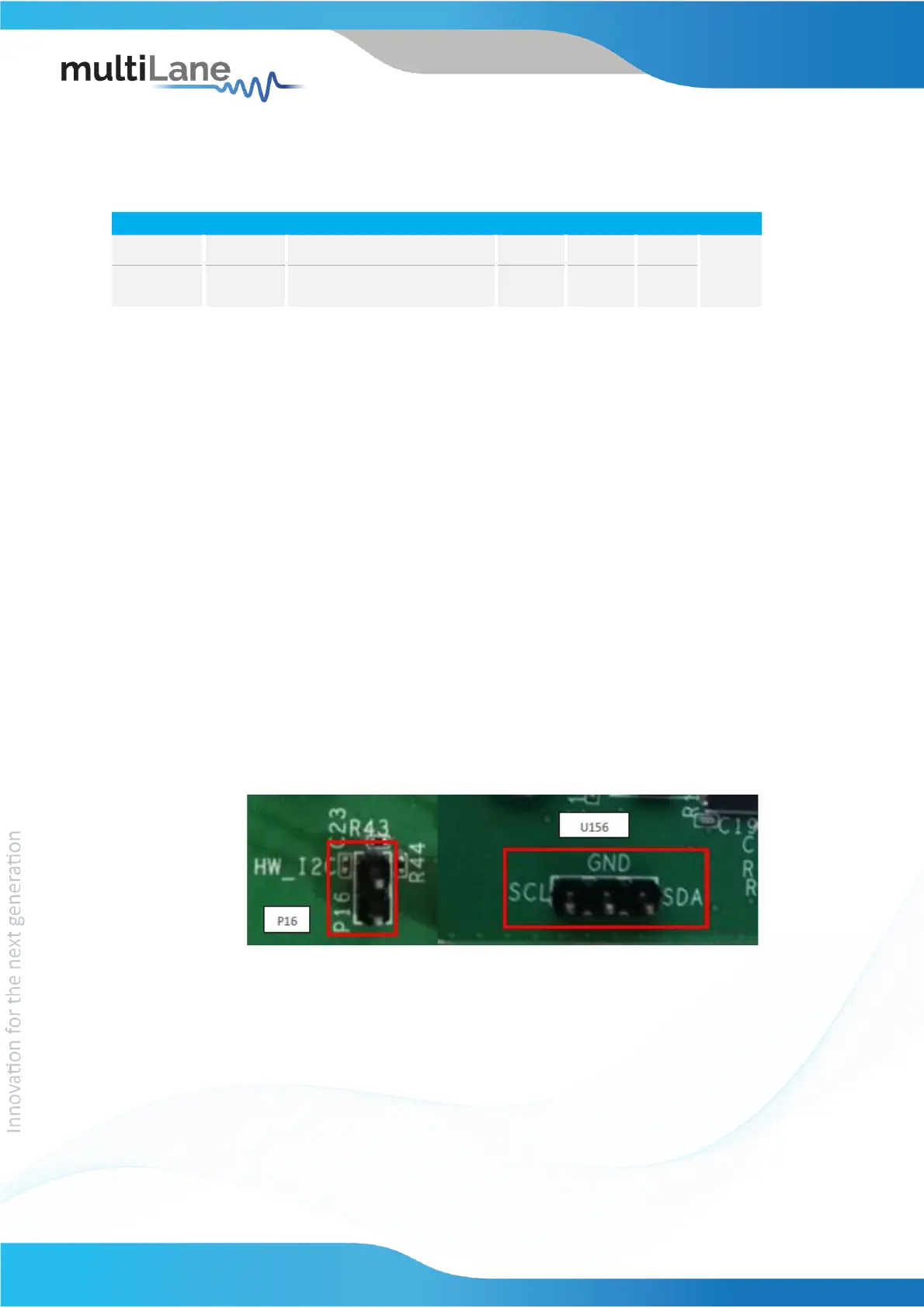
The I2C bus can be accessed externally using U156 pins. In this case a jumper should be
placed on pin header P16 (HW_I2C) shown in the image below.
Figure 1: External I2C
3.4.2 External HW Control
Also Low Speed Signals are controllable using an external source, this can be done
through J4 pin header. In this case a jumper should be placed on pin header J3
(HW_CTRL) shown in the image below.