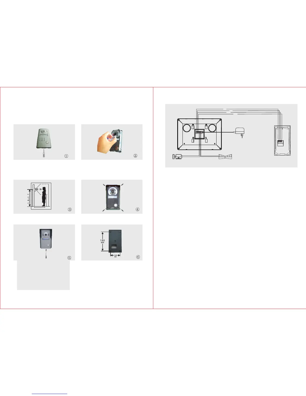
B. Outdoor Unit
4
3
1) Take off the screws on the bottom and remove the front cover.
2) Take off the ‘Room No,’ lid and write down your respective room/block
number and cover it again with the lid.
3) Install the Outdoor Unit 1.4m ~ 1.7m above the ground level
(according to the camera effect ).Avoid direct sunlight.
4) Fasten the outdoor unit on the wall with the enclosed screws (4x30BA).
5) Cover the zinc alloy panel and tighten up the screws on the bottom.
The enclosed cable is 15m, RVV4 connecting wire can be chosen if you
2
x 0.5mm
want to lengthen it to 15m~50m, RVV4 connecting wire can be chosen
2
x 0.75mm
if you want to lengthen it to 50m~100m.
Connect the wiring terminals 1,2,3,4 of indoor unit with wiring terminals 1,2,3,4 of
outdoor unit . The wiring terminals 5 & 6 of indoor unit are connected with electric
lock through RVV2 1.0 connecting wire. The wiring terminals 7 & 8 of indoor
2
x mm
unit are connected with the gate through RVV 2 x1.0mm connecting wire.
2
Please refer to the wiring diagram during connection.
Wiring Requirement
C. Wiring Diagram
Cables:
1.Audio wire
2.Ground wire
3.Video wire
4.Power wire
Outdoor Unit
Electronic-lock
Indoor Unit
Gate Unlock
1
2
3
4
AC100-240V
50HZ/60HZ
DC12V
111
222
333
444555666777 888
m
Talking distance<40cm