Do you have a question about the MultiTrode MTRA-FSP and is the answer not in the manual?
Guidance for obtaining working knowledge of the product for optimal application performance and future reference.
Explanation of symbols used in the manual: DANGER, WARNING, and NOTE, indicating severity of non-compliance.
Safety warnings regarding qualified personnel for installation and servicing, and no user-serviceable parts.
Details on available power supply options (AC, DC backup) and recommended protection device ratings.
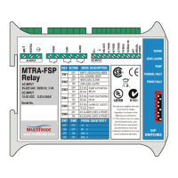
Configuration options for the MTRA-FSP using DIP switches, detailing modes, alarms, and sensitivity.
Describes the pump operation for emptying a well, including activation, deactivation, and alarm conditions.
Details pump operation for filling a well, including activation, deactivation, and alarm triggers based on liquid levels.
How the AL Probe detects high/low levels and triggers alarms, including output configuration (NO/NC, flashing).
Covers Thermal and Seal alarms, including thermal sensor input and its effect on pump operation and indicators.
Explains how to manually start and stop the pump using external pushbuttons and its reversion to auto mode.
Adjusting probe sensitivity using DIP switches 7 & 8 for different liquid conductivity detection.
Using DIP switches 3 and 5 to set delays, preventing spurious pump starts and alarm activations.
| Brand | MultiTrode |
|---|---|
| Model | MTRA-FSP |
| Category | Other |
| Language | English |