16
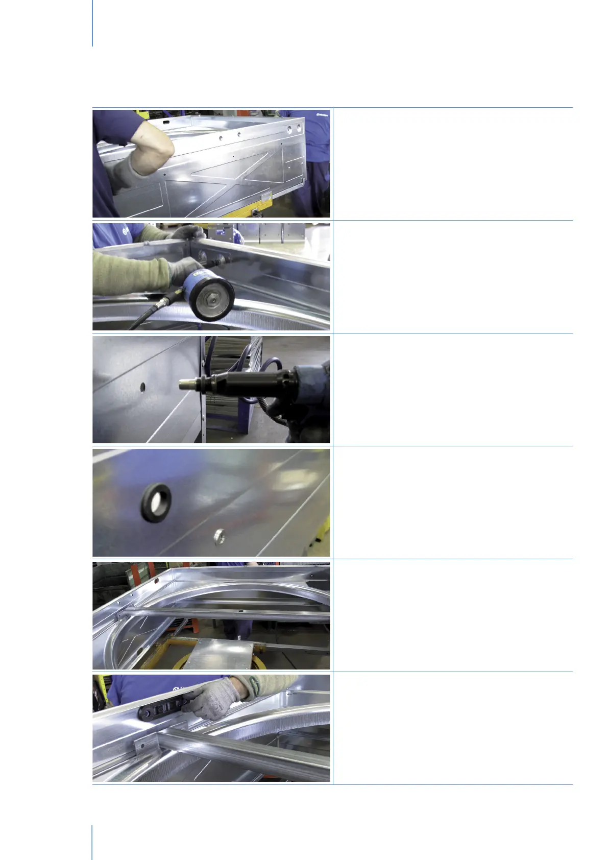
Place the top panel (ref.1.5/Body) with motor support
in correspondence with motor slot on the Venturi. Then
fix it to side panels with qty. 4 pop rivets for side and
to Venturi with qty.1 pop rivet.
Place the qty.2 short threaded bushes (ref.7.2/
Bolts&nuts) on the top panel by using inserting
machine (ref.2/Assembling Tools).
Place long threaded bushes (ref.7.2/Bolts&nuts) in
correspondence of proper holes around the housing.
Qty. 2 long threaded bushes for each panel.
Make sure that Venturi and each panel are joined by
the long threaded bushes.
Place the rubber grommet (ref.7.15/Bolts&nuts)
for electric cable protection on the side panel in
correspondence with the motor slot.
The propeller central support (ref.1.2/Body) shall be
fixed to housing by means of qty. 4 screws, qty. 2
oval plates, qty. 4 toothed washers and qty. 4 nuts
(ref.7.4/Bolts&nuts).
Place the oval plates between propeller central
support and panels.
Assembling guidelinesChapter3