!Caution
Inverting the PCB
Make sure not to impose any abnormal mechanical shocks to
the PCB.
4. Optimum Solder Amount for Reflow Soldering
4-1. Overly thick application of solder paste results in a
excessive solder fillet height.
This makes the chip more susceptible to mechanical
and thermal stress on the board and may cause the
chips to crack.
4-2. Too little solder paste results in a lack of adhesive
strength on the termination, which may result in
chips breaking loose from the PCB.
4-3. Please confirm that solder has been applied
smoothly to the termination.
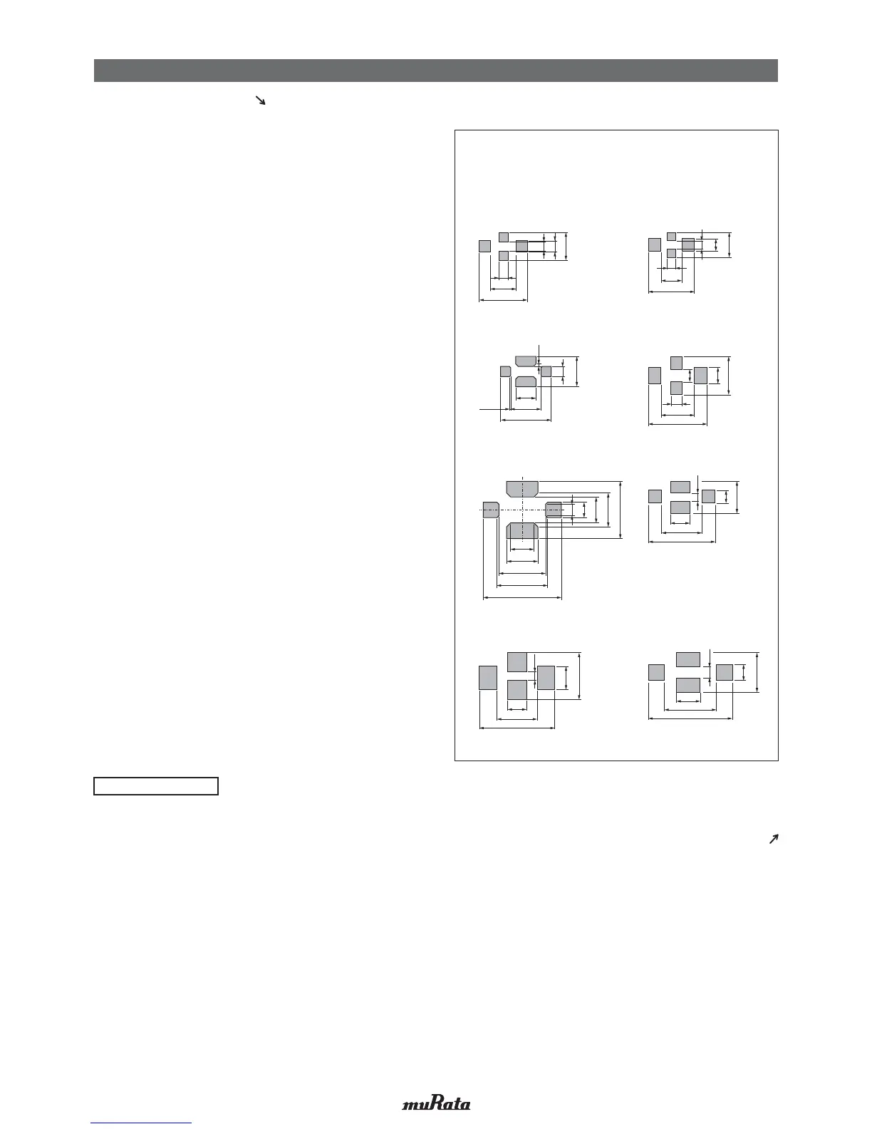
<Applicable to NFM Series>
Continued from the preceding page.
Continued on the following page.
100-150μm: NFM15/18/21/3D/31
100-200μm: NFM41
[Guideline of solder paste thickness]
2.6
2.5
4.4
1.0
0.6
1.2
NFM21PS
2.0
2.5
3.9
1.0
0.6
0.8
NFM3DCC/3DPC
NFM31PC/31KC
NFM18PS
2.6
3.5
5.5
1.5
0.6
1.0
NFM41CC/41PC
NFM15CC/15PC
2.2
1.0
0.4
0.6
1.2
NFM18CC/18PC
0.4
NFM21CC/21PC
1.4
2.6
0.6
0.8
0.6
1.9
0.8
0.4
0.1
1.2
1.20.05
2.0
0.85
1.85
0.6
1.6
1.2
2.6
1.25
0.4
1.8
0.8
0.25
0.7
1.3
0.25
0.3
0.75
!
Note
• Please read rating and
!
CAUTION (for storage, operating, rating, soldering, mounting and handling) in this catalog to prevent smoking and/or burning, etc.
• This catalog has only typical specifications. Therefore, please approve our product specifications or transact the approval sheet for product specifications before ordering.