!Caution
4-1. Reflow Soldering
1. When sudden heat is applied to the components, the
mechanical strength of the components will decrease
because a sudden temperature change causes
deformation inside the components. In order to prevent
mechanical damage to the components, preheating is
required for both the components and the PCB.
Preheating conditions are shown in table 1. It is required to
keep the temperature dierential between the solder and
the components surface (ΔT) as small as possible.
2. When components are immersed in solvent aer mounting,
be sure to maintain the temperature dierence (ΔT)
between the component and the solvent within the range
shown in table 1.
Recommended Conditions
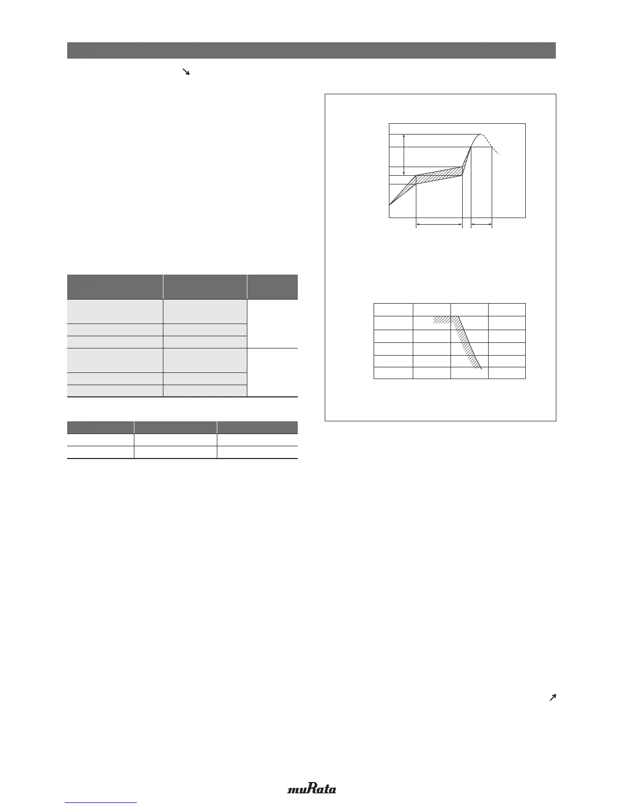
[Example of Temperature Conditions for Reflow Soldering]
[Allowable Reflow Soldering Temperature and Time]
In the case of repeated soldering, the accumulated
soldering time must be within the range shown above.
Temperature
Incase of Lead Free Solder
( ): In case of Pb-Sn Solder
Soldering Time (s)
260
270
280
250
240
230
220
0 30 60 90 120
Soldering Temperature (°C)
Peak Temperature
Atmosphere
Pb-Sn Solder
230 to 250°C
Air
Lead Free Solder
240 to 260°C
Air or N2
60-120 seconds 30-60 seconds
ΔT
Gradual
Cooling
Soldering
Preheating
220°C (200°C)
190°C (170°C)
170°C (150°C)
150°C (130°C)
Time
Temperature (°C)
Peak Temperature
Pb-Sn Solder: Sn-37Pb
Lead Free Solder: Sn-3.0Ag-0.5Cu
3. When a capacitor is mounted at a temperature lower
than the peak reflow temperature recommended by the
solder manufacturer, the following quality problems can
occur. Consider factors such as the placement of
peripheral components and the reflow temperature
setting to prevent the capacitor’s reflow temperature
from dropping below the peak temperature specified. Be
sure to evaluate the mounting situation beforehand and
verify that none of the following problems occur.
F0-.',1-*"#05#22 '*'27
F-*"#04-'"1
F-11' *#-!!300#,!#-$5&'1)#0',%
F0-.', -,"',%120#,%2&
F0-.',1#*$Q*'%,+#,2.0-.#02'#1
F-11' *#-!!300#,!#-$2-+ 12-,#1,"G-01&'x',%-,
the land patterns of the circuit board
GRM/GJM/GQM/GR3/
GRJ/KRM/LLR/NFM/GR7
02/03/15/18/21/31
LLL
02/03/15/18/1U/21/31
ZRB 15/18
GR3/GRJ/GRM/KR3/KRM
GA2/GA3/GR4
32/42/43/52/55
LLA/LLM 18/21/31
GQM 22
ΔT
<
=
190°C
ΔT
<
=
130°C
Series
Chip Dimension Code
(L/W)
Temperature
Dierential
Table 1
Continued from the preceding page.
Continued on the following page.
!
Note
• Please read rating and
!
CAUTION (for storage, operating, rating, soldering, mounting and handling) in this catalog to prevent smoking and/or burning, etc.
• This catalog has only typical specifications. Therefore, please approve our product specifications or transact the approval sheet for product specifications before ordering.