EasyManua.ls Logo

MURO FDVL41 - Operating Instructions

Default Icon
8 pages
Print Icon
To Next Page IconTo Next Page
To Previous Page IconTo Previous Page
Loading...
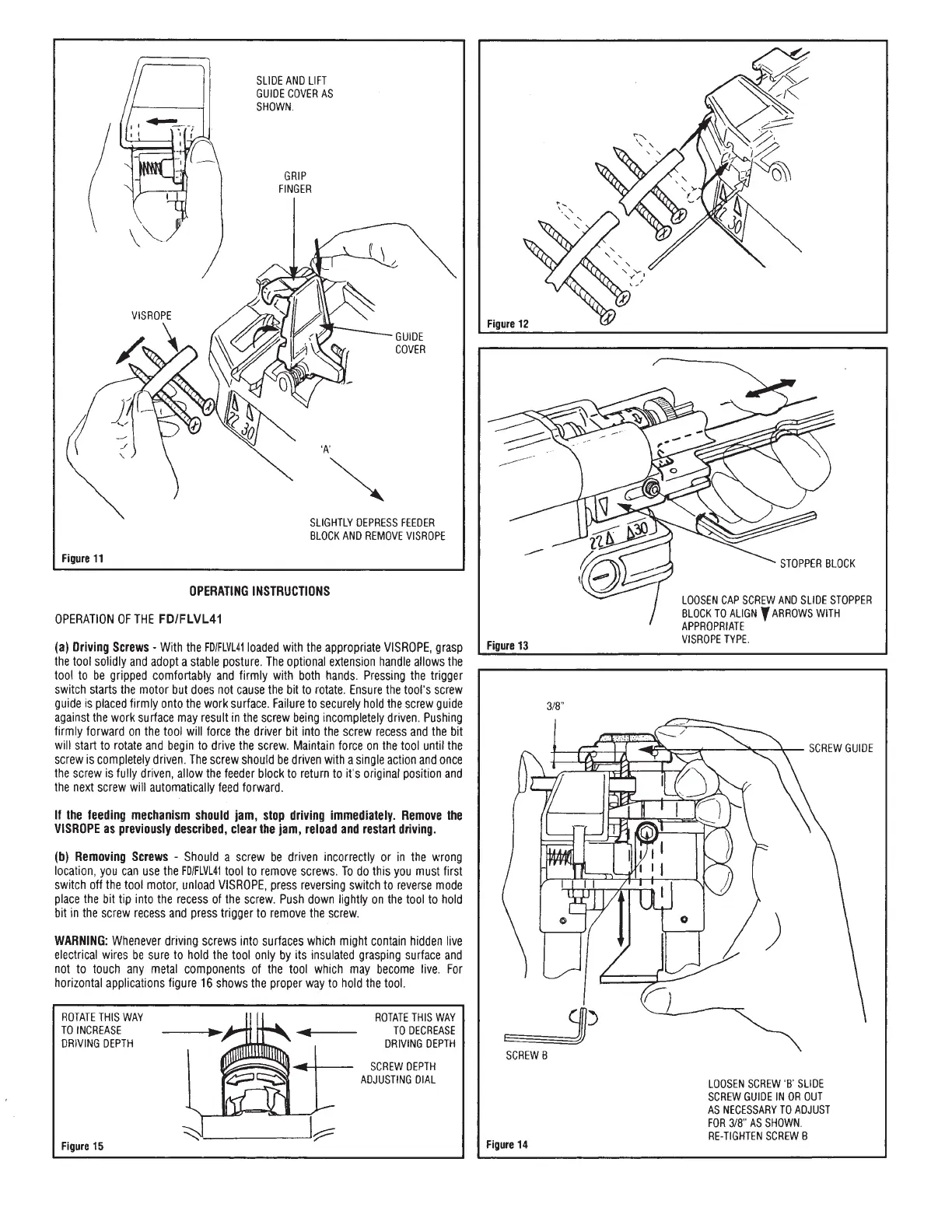
SLIDE
AND
LIFT
GUIDE
COVER
AS
SHOWN.
GRIP
FINGER
SLIGHTLY
DEPRESS
FEEDER
BLOCK
AND
REMOVE
VISROPE
Figure
11
OPERATING
INSTRUCTIONS
OPERATION
OF
THE
FD/FLVL41
(a)
Driving
Screws
-
With
the
FD/FLVL41
loaded
with
the
appropriate
VISROPE,
grasp
the
tool
solidly
and
adopt
a
stable
posture.
The
optional
extension
handle
allows
the
tool
to
be
gripped
comfortably
and
firmly
with
both
hands.
Pressing
the
trigger
switch
starts
the
motor
but
does
not
cause
the
bit
to
rotate.
Ensure
the
tool's
screw
guide
is
placed
firmly
onto
the
work
surface.
Failure
to
securely
hold
the
screw
guide
against
the
work
surface
may
result
in
the
screw
being
incompletely
driven.
Pushing
firmly
forward
on
the
tool
will
force
the
driver
bit
into
the
screw
recess
and
the
bit
will
start
to
rotate
and
begin
to
drive
the
screw.
Maintain
force
on
the
tool
until
the
screw
is
completely
driven.
The
screw
should
be
driven
with
a
single
action
and
once
the
screw
is
fully
driven,
allow
the
feeder
block
to
return
to
it's
original
position
and
the
next
screw
will
automatically
feed
forward.
If
the
feeding
mechanism
should
jam,
stop
driving
immediately.
Remove
the
VISROPE
as
previously
described,
clear
the
jam,
reload
and
restart
driving.
(b)
Removing
Screws
-
Should
a
screw
be
driven
incorrectly
or
in
the
wrong
location,
you
can use
the
FD/FLVL41
tool
to
remove
screws.
To
do
this
you
must
first
switch
off
the
tool
motor,
unload
VISROPE,
press
reversing
switch
to
reverse
mode
place
the
bit
tip
into
the
recess
of
the
screw.
Push
down
lightly
on
the
tool
to
hold
bit
in
the
screw
recess
and
press
trigger
to
remove
the
screw.
WARNING:
Whenever
driving
screws
into
surfaces
which
might
contain
hidden
live
electrical
wires
be
sure
to
hold
the
tool
only
by
its
insulated
grasping
surface
and
not
to
touch
any
metal
components
of
the
tool
which
may
become
live.
For
horizontal
applications
figure
16
shows
the
proper
way
to
hold
the
tool.
ROTATE
THIS
WAY
TO
INCREASE
DRIVING
DEPTH
ROTATE
THIS
WAY
TO
DECREASE
DRIVING
DEPTH
SCREW
DEPTH
ADJUSTING
DIAL
Figure
15
Figure
12
STOPPER
BLOCK
LOOSEN
CAP
SCREW
AND
SLIDE
STOPPER
BLOCK
TO
ALIGN
Y
ARROWS
WITH
APPROPRIATE
Figure
13
VISROPE
TYPE.
SCREW
GUIDE
aT
i
Dí
i
L
SCREW
B
LOOSEN
SCREW
'B'
SLIDE
SCREW
GUIDE
IN
OR
OUT
AS
NECESSARY
TO
ADJUST
FOR
3/8"
AS
SHOWN.
.
RE-TIGHTEN
SCREW
B
Figure
14