3.2.2. Green and red indicator lights on
Shows filter needs replacing (v. § 7.3)
3.2.3. Red indicator light on and gr
een indicator light off :
Shows there is no filter or there is an error (v. § 6.3)
41
3.3. Main screen
The first line shows the day, date and time. The system automatically controls the switch between winter and summer times.
The first rectangle shows the ventilator status :
means the ventilator is operating normally
means the ventilator has stopped.
A gauge with 8 strokes represents the airflow.
The second rectangle displays a thermometer to show the temperature required.
The final rectangle shows whether it is day or night and the season. The system operates according to 4 key modes: :
Winter /day see § 4.1.1.1 Winter /night see § 4.1.1.2
Summer /day see § 4.1.1.3 Summer /night see § 4.1.1.4.
The line of text just below shows information about the operation of the ATU (see § 6). In the event of a problem,
the telephone number for your region is displayed.
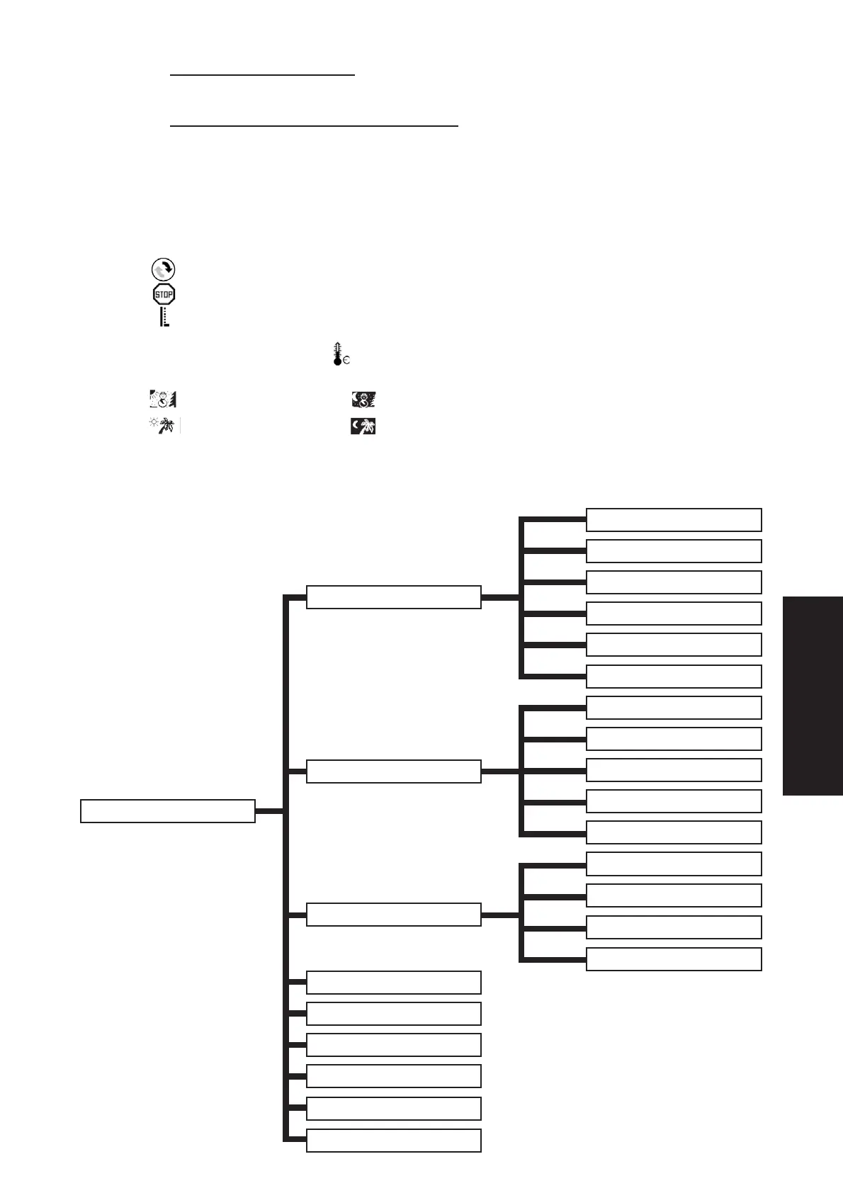
3.4. Tree structure
Main screen Pg. 41
Factory settings Pg. 45
Date and time control Pg. 45
Language choice Pg. 45
Country choice Pg. 45
Region choice Pg 45
System settings Pg. 45
Automatic Pg. 42
Temporary Pg. 43
Rapid Pg. 43
Absent Pg. 43
Summer Pg. 43
Winter Pg 44
General flow Pg. 44
Day flow Pg. 44
Night flow Pg. 44
Temporary flow Pg. 44
Temporary duration Pg. 44
T° Winter Pg. 44
T° Summer Pg. 44
T° Absence Pg. 44
Max air T° Pg. 44
Modus selection Pg. 42
Airflow control Pg. 44
Temperature control Pg. 44
ENGLISH