MAINTENANCE
25
F–030767L
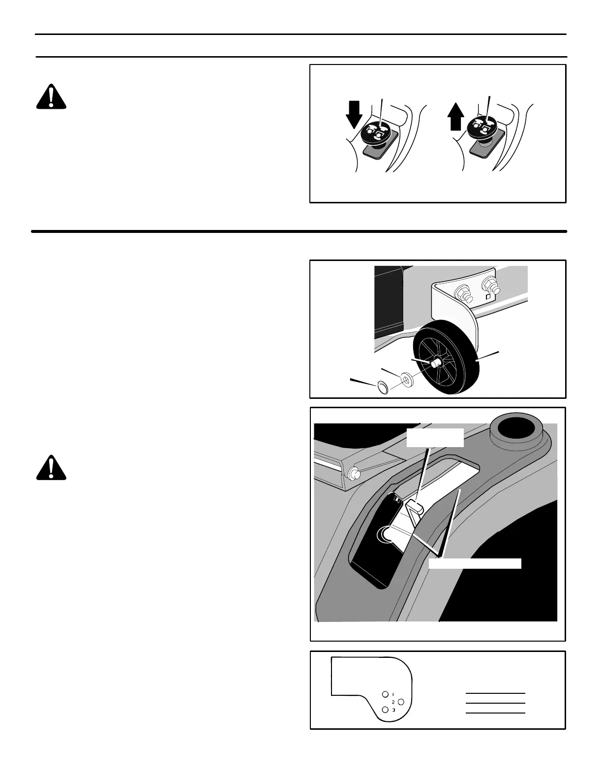
HOW TO CHECK THE BLADE ROTATION CONTROL
WARNING: To prevent an injury, the blade rotation
control must operate correctly.
1. With the engine running, move the blade rotation control to
the ENGAGED positon (Figure 18).
2. Move the blade rotation control to the DISENGAGE position.
All movement will stop within five seconds. If there is movement
of the belt or if the blades continue to rotate, engage and disen-
gage the blade rotation control five times This will remove
any excess rubber from a new mower drive belt. If you need
assistance, take the unit to an authorized service center.
Figure 18
Engage Position
Disengage Position
HOW TO ADJUST THE GAUGE WHEELS
The axle bolts for the gauge wheels were mounted in the LOW cut
position. To change the position of the gauge wheels, move the axle
bolts as follows.
IMPORTANT: Before you adjust the gauge wheels, you must do
the following. Make sure the mower housing is level. Make sure
the height of cut is set at the height you want for your lawn.
Mow a short distance on a flat level area and look at the area
that was cut. If the mower housing does not cut level, see the
instructions “How To Level The Mower Housing.”
WARNING: Before you make an inspection, adjust-
ment, or repair to the unit, disconnect the wire to the
spark plug. Remove the spark plug wire to prevent
the engine from starting by accident.
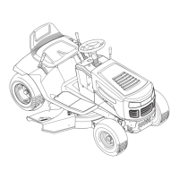
1. Remove the gauge wheels (Figure 19).
2. Mow a short distance on a flat level area to check the level of
cut and the height of cut. Look at the cutting height position
number on the height-of-cut indicator (Figure 20).
3. Look at each gauge wheel bracket. There are 3 holes in each
bracket and a number next to each hole. The number for the
cutting height position on the height-of-cut indicator indicates
the correct hole to use on each gauge wheel bracket
(Figure 21).
4. Assemble the axle bolts to the gauge wheel brackets using
the correct hole in the bracket as indicated (Figure 21).
NOTE: If the height-of-cut position is changed, you must move
the gauge wheels to the correct hole (Figure 21) to keep a level
height of cut.
Gauge Wheel
Figure 19
Locking
Ring
Washer
Axle Bolt
Figure 20
Cutting Height Positions
Height-Of-Cut
Indicator
Wheel Bracket
Hole No.
Cutting Height
Position No.
1 1
2 2
3 3,4,5,6
Figure 21
Gauge
Wheel Bracket