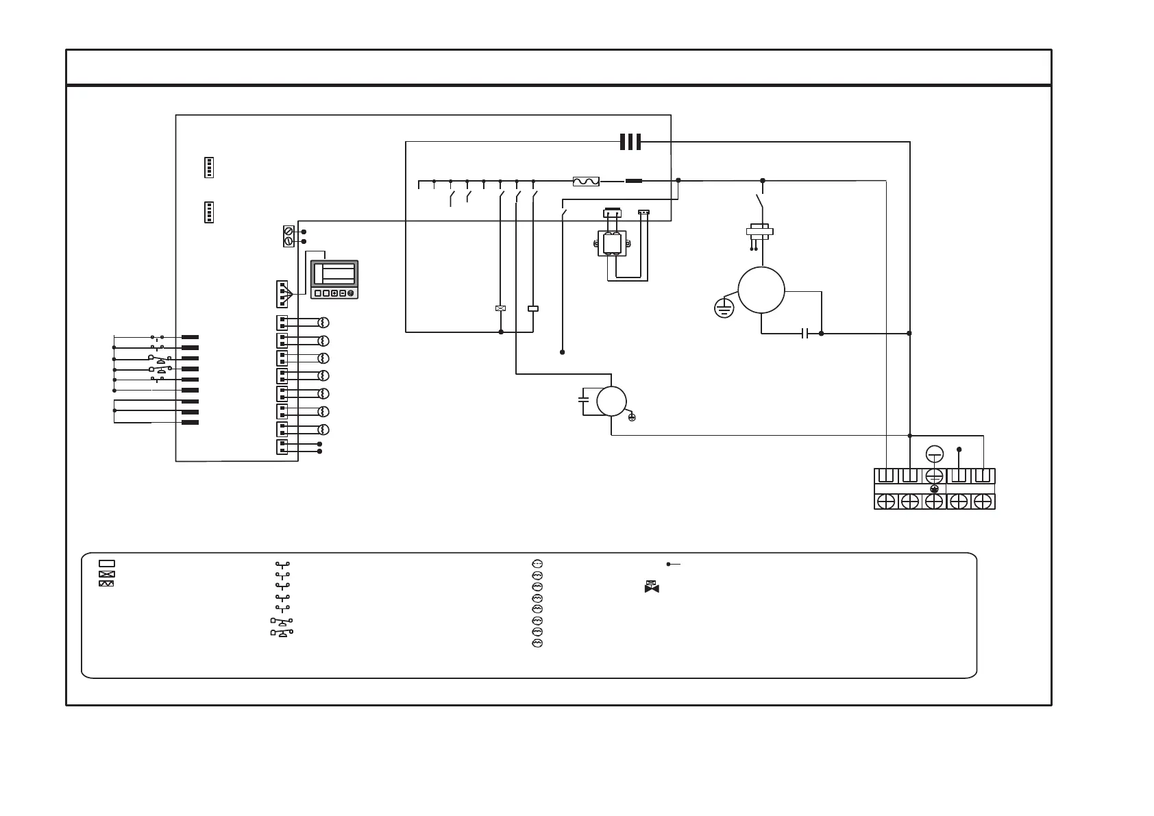
Wiring diagram(JXT- MK 6019- EG- 02)
Mk6019
N
Fuse(220V/3.15A)
L
KM1
TRAN-IN TRAN-OUT
Online signaB
MK4090
CN4
定时 功能
Transformer
P3 P4
Red
C
compressor
Blue
SW4
SW2
HP1
LP1
SW3
SW5
SW1
IN7
IN6
IN5
IN4
IN3
COM
IN2
IN1
Wire controller
T1
T2
T3
T4
T5
T6
VA1
KM1
P5
capacitance
Red
Fan
S
white
R
capacitance
Blue
W_COM
T7
T8
P3
P4
orange
White
P5
L
N 1 2
Legend
:
:A.C. Contactor/relay coil
:Electric driven valve coil
SW1
SW2
:Emergency switch(closed)
:Air conditioning on line switch (closed)
T1
T
:Water tank temp.
P5
T2
T
:Water outlet temp.
:
Water cycle pump power
Unit power input
( 220 V/ 1 PH/ 50
Hz)
Water cycle pump
power outpur
( 220 V/ 1 PH/ 50
Hz)
:Crankshaft electric heating
SW3
KM1
:Compressor A.C. Contactor
SW4
:Water flow switch
:
Phase sequence protection
T3
T
:coil temp.
T4
T
:discharge temp.
E-VALVE1 : main electronic expansion valve
E-VALVE2
: auxiliary electronic expansion valve
VA1
:four way valve
SW5
:Electric heating overheating protection
(closed) T5
T
:suction temp.
CH1
:crankshaft electric heating
HP1
LP1
:high pressure protection switch
:low pressure protection switch
T6
T
:Ambient temp.
T7
T
:Water inlet temp.
T8
T
:compressor current detection