Looping Delay: Inputs and outputs
All CV inputs are calibrated for a range of +/- 5V. Voltages outside of this range are
tolerated, but will be clamped.
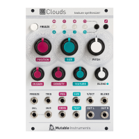
1. FREEZE gate input. When the input gate signal is high, stops the recording of incom-
ing audio, just as latching the FREEZE button would do.
2. CLOCK (TRIGGER). Sending a trigger on the TRIG input creates a clock-synchro-
nized loop (when FREEZE is enabled) or stuttering effect – equivalent to applying a
tempo-synchronized decaying envelope on the POSITION parameter.
3. 4. Pre-Delay (POSITION) and SIZE CV inputs. SIZE controls the size of the overlap-
ping windows used for pitch-shifting and time-stretching – from an extremely grainy
“drilling” sound to smooth bits of loops. Delay time changes are now much faster (there
is less slew on the knob and CV value). Modulating POSITION will create effects similar
to vinyl scratching or manual manipulation of tape
5. Grain transposition (PITCH) CV input, with V/Oct response.
6. BLEND CV input. This CV input can control one of the following functions depending
on the active blending parameter: dry/wet balance, grain stereo spread, feedback
amount and reverb amount.
7. 8. Stereo audio input. When no patch cable is inserted in the right channel input, this
input will receive the signal from the left channel.
9. 10. Diffision (DENSITY) and Filter (TEXTURE) CV inputs.
Looping Delay: Controls (Cont.)
I. LOW PASS/HIGH PASS FILTER (TEXTURE) acts as a low-pass/high-pass filter.
J. BLEND knob. This multi-function knob is described in the Blending parameters sec-
tion.
K. Indicator LEDs. They work as an input vu-meter. When FREEZE is active, they moni-
tor the output level. Soft-clipping occurs when the last LED is on. They can also indicate
the quality setting (red), the function assigned to the BLEND knob (green), or the value
of the four blending parameters (multicolor).